SLO Build
Moderators: pompeiisneaks, Colossal
SLO Build
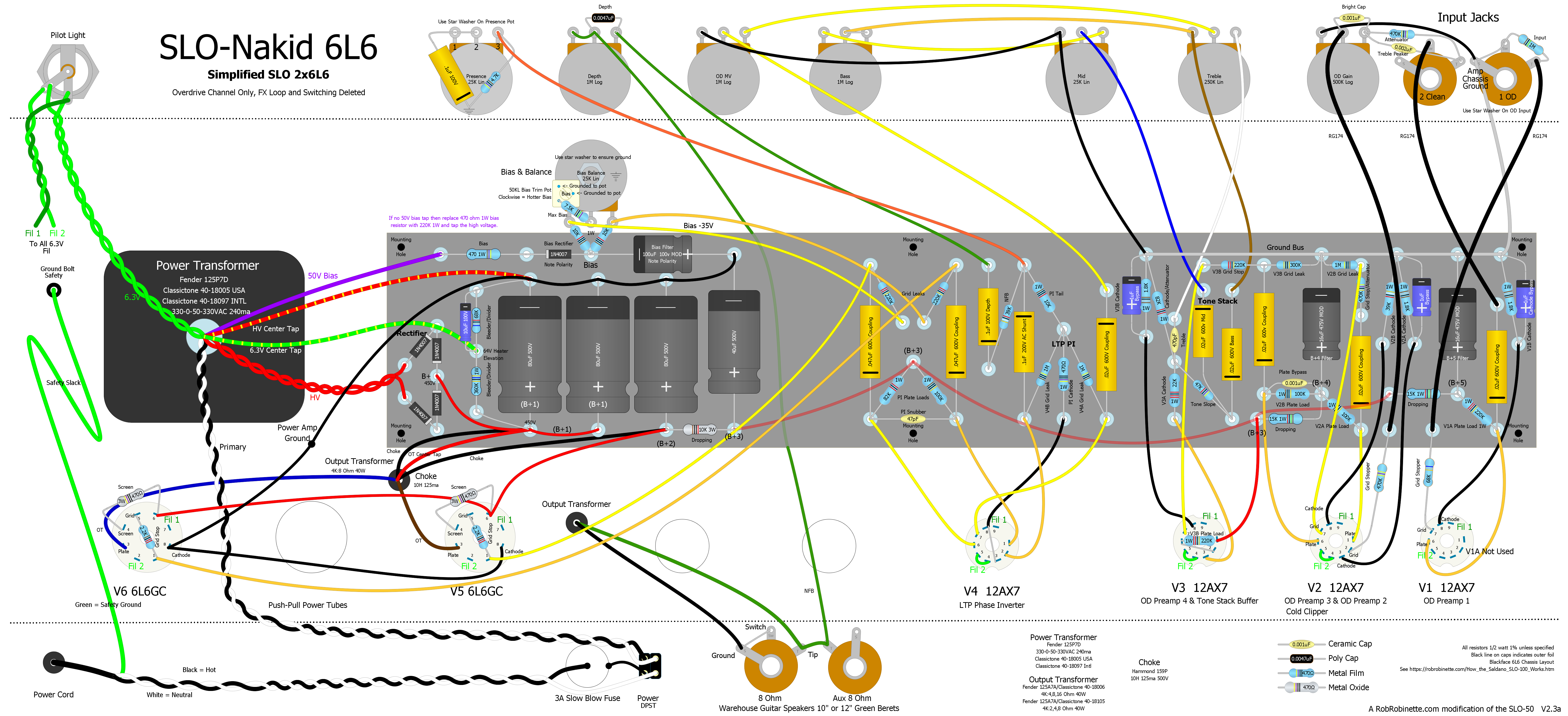
I'd like to build the SLO-Nakid 6L6 40 Watt, I've accquired a 501426 PT from a Wurlitzer organ that had a pair of 6l6s as a novice builder I'm not to sure about the HV windings of which to use, there isn't to much info on them on line. I assume the reds are higher than my meter can take so i measured the what apperar to be center taps. red and red/green get about 505v and the red red/yellow are 377v and what look like a second set of yellows or are they brown? is 13.65v
You do not have the required permissions to view the files attached to this post.
-
martin manning

- Posts: 14058
- Joined: Sun Jul 06, 2008 12:43 am
- Location: 39°06' N 84°30' W
Re: SLO Build
Follow the standard procedure for dealing with an unknown PT:
Group leads the have continuity/finite resistance together
Check each winding for shorts to the core
Identify the primary if possible, otherwise guess
Apply low voltage AC to the primary, ~1/10 of assumed line voltage
Measure voltages on the other windings and identify center and other taps on windings with three or more leads
Scale all voltages up by (line voltage/applied voltage)
Confirm assumption of primary leads by comparing measurements to expected voltages for HV and heater windings
Look like you have already grouped the leads.
If I had to guess I'd say
Black pair is the primary
Green pair is 6.3V heater with green/yellow CT
Yellow pair is 5V rectifier
Red pair is HV with red/yellow CT, red/green for bias(?)
Red/yellow and brown is some auxiliary winding
Re: SLO Build
https://robrobinette.com/images/Guitar/ ... Layout.png "Red pair is HV with red/yellow CT, red/green for bias(?)" how do i tell if i can use the bias if it is a bias in the way the layout shows?
-
martin manning
- Posts: 14058
- Joined: Sun Jul 06, 2008 12:43 am
- Location: 39°06' N 84°30' W
Re: SLO Build
Need to understand exactly what voltages you have. Can you make a schematic diagram of the transformer, something like this?
You do not have the required permissions to view the files attached to this post.

Re: SLO Build
This is good progress. I think not all of the information is lined up the way we need it. The 5V, 6.3V and 12V windings appear to be settled. For the other leads there's a little more work to do.
I'm reasonably certain you've told us that the two Red leads are the outer ends of the winding and the Red/Yellow is the center tap. While it is possible the voltage between the two Red leads is 1492V, I'm thinking it is 746V. Let's see if you can get the voltages organized differently. Choose one Red lead (let's call it Red1) and clip one meter lead to it. Then clip the other meter lead to each wire and tell us the voltages between Red1 and:
Red/Green1
Red/Green2
Red/Yellow
Yellow/Brown
Brown1
Brown2
Red2
Re: SLO Build
I think we've got some good information and some things that don't make sense to me. I have the sense that you aren't so familiar with power transformers, so I may be covering some basics that you already know. Please forgive me if I did not guess correctly. Also, due to the age of the transformer, the colors of some of the leads may have faded, making it harder to identify the color -- this is with respect to grouping the leads.
A transformer is, essentially, two or more relatively long pieces of wire wrapped around a central core. The wrapped wires (windings) and core are stuffed inside a bunch of metal plates -- the laminations ("lams") -- that form the outer metal block. The open sides of the lams are covered with end bells. There are leads attached to the windings that emerge through the end bells. There will always be a pair of leads at the end of each winding. Sometimes, there will be additional leads attached to a winding midway between the ends -- these are called "taps." All test measurements should be AC voltage.
Your transformer shows the leads all coming out of only one end bell. There are two holes that help to make logical wire lead groups.
On the right side, there are seven wires emerging from the hole. The colors used are typical and this is what I think you have coming through the right side hole:
A) Black + Black. This pair is the primary connection that connects to the wall supply using a fuse on the hot lead for safety. In the US and Canada, the wall supply is about 120VAC. Actual voltage will vary throughout the day and the variation will have a minor affect on the secondary voltages. There is only one primary pair. The rest are all secondary windings or taps.
B) Yellow + Yellow. The Yellow pair is typically the 5VAC winding to supply filament voltage to the rectifier. You originally indicated 5.3V and that seems about right. The voltage will drop under load, when you have the leads connected to a tube socket with a 5V rectifier tube.This should be an isolated winding, not connected to any other winding. I don't understand how you are getting a voltage reading between the Yellow leads and the Red leads -- indicated in your later postings. Something isn't right about that.
C)Green + Green/Yellow + Green. This is a center-tapped 6.3VAC filament supply winding. You originally indicted 6.6 - 3.6 - 6.6, as written suggests a 12.6 filament winding. I think this is really 3.3 - 0 - 3.3V. Add the two outer legs for a total of 6.6V supplied by this winding. Confirm by clipping your meter leads to the two Green wires and you should see 6.6VAC. It provides filament or heater voltage to the preamp and power tubes. This, also, should be an isolated winding. I don't understand how you are getting a voltage reading connected to the Red leads. As with the rectifier filament winding, I don't understand how you can get voltage from the Red leads.
That completes the right side hole. On to the left side.
On the left, there are 6 leads. I believe there are two windings here. One is the high voltage winding and I believe the other is a 12.6VAC filament supply:
D) Red + Red/Yellow + Red/Green + Red. This group is the high voltage winding. Sometimes you'll see us write "HT" for high tension. HT and HV are the same thing. We know that the Red/Yellow is the center tap ("CT".) We know this because you reported 746VAC between the two Red leads and half of 746V = 373V. You reported about 373V from each Red to the Red/Yellow. You can confirm this by clipping one meter lead to the CT and the other to each Red in turn. You should see about 373VAC for both readings. CT really does mean that lead is attached half way on the winding. Red/Green appears to be a screen supply -- I'm not clear of the actual voltage but the reported voltage readings tell us it is between one of the Red leads and the CT. For a guitar amp, you probably won't be using the Red/Green. Edit: you measured 746 from Red to Red, so the winding is 373-0-373 and probably when under load will be more like 360-0-360. This seems like a reasonable HT supply for a guitar amp. Depending on choice of rectifier, you should expect B+ to be around 450-475VDC.
E) Brown + Brown/Yellow. You previously indicated 13.6V. I think this is a 12.6V filament supply. (The voltage always drops under load.) It could potentially be used as the filament supply for one or more 12V preamp tubes (like 12AX7) or a pair (or pairs) of 6.3V filament tubes wired in series.
What isn't clear is how many and what tubes you can support with various windings. These were designed to supply an amount of current and we don't know what that is though there are ways to make reasonable guesses. You say the transformer is from an organ. This is good news. Tube-driven organs typically have many tubes. It is reasonable to assume you can power a pair of 6L6 power tubes and several preamp tubes.
One more note on reading voltages from the Red-Red winding. If you really are seeing continuity between either of the Red leads and the other windings, it may be indicating a short, in which case your transformer isn't usable. You can confirm continuity with your meter by measuring (disconnected from electric power) Ohms between the various wires. You should see and open load between the HT winding and the other windings. If your meter has a continuity setting the gives you an audible beep, you can use that setting and you should hear nothing.
Re: SLO Build
yeah i think things are off but again I'm a novice and this beeping makes it more confusing.
You do not have the required permissions to view the files attached to this post.
-
johnnyreece

- Posts: 1061
- Joined: Thu Jan 26, 2012 2:05 am
- Location: New Castle, IN
Re: SLO Build
Just to also muck things up...I've used an old radio transformer before, and the colors did not match normal tendencies. The primaries were white, secondaries were green, and the CT was green/yellow. The 6.3V filaments were black, and the 5V filaments were yellow (something that actually matches). Just saying this to say - don't make any assumptions on an old PT. Ohm it out first, then make educated guesses from there. This is mostly for future reference; it seems Phil has you sorted out.
Re: SLO Build
Red-Red no beep seems impossible. Bad contact with the meter leads? At least twice you reported 746V between the two Reds. (Remember wall voltage will vary, affecting secondary voltage. Not something of concern if you see readings that are up to about +/- 4% from a prior reading.) Also, seems quite unlikely that a pair of red leads is something other than two ends of the same winding. Red is a standard color for HT winding. OK, keep in mind what Johnny says, don't assume, but we already have a reported voltage using the pair of Black leads as primary.
Other continuity beeps are as predicted, which is good!
From either of the Red leads, is there continuity with any other leads, excluding the Red/Yellow and Red/Green?
It is a good idea at this point to get Ohms readings for each winding and post those.
I had a brain cramp earlier on the Red/Green. What is voltage between Red/Green and Red/Yellow? I'm expecting about 125V. It's about 3x what you'd want for a bias supply but it is possible to dump the excess voltage. However, it might be better to simply tap the HV supply like you commonly see in a Marshall.
It is OK that you are a novice. One thing that gets done in a forum like this is to get people started.
-
sluckey
- Posts: 3432
- Joined: Sun Jul 22, 2007 7:48 pm
- Location: Mobile, AL
- Contact:
1 others liked this
Re: SLO Build
That's normal for a continuity check. The continuity check is meant for open and short conditions, not resistance checks. A meter has a resistance threshold to determine whether to beep or not. For example my Klein MM700 threshold is 50Ω. Quote from my manual...
"Test for continuity by connecting conductor or circuit with test
leads. If resistance is measured less than 50Ω, an audible signal
will sound and display will show a resistance value indicating
continuity. If circuit is open, display will show "OL"."
I'm sure the actual DCR measured between the red leads is much greater than the meter's threshold and that's why there is no beep. Better to check in resistance mode. Save the continuity mode to troubleshoot your boat trailer wiring.
Re: SLO Build
i rehooked up the reds still no beep and noticed .055 the rest of the ohm readings are on the "Tue May 13, 2025 10:34 am" post at the bottom.