5E3 - First build, first dud
Moderators: pompeiisneaks, Colossal
-
patrick620
- Posts: 46
- Joined: Mon Feb 14, 2011 4:10 am
- Location: Wichita, Ks.
- Contact:
Re: 5E3 - First build, first dud
Soldering is an art form of sorts that takes experience, practice, and even better, some amount of in person training before diving into a project. I would suggest you watch some tutorials and practice on a junk piece of equipment or make a practice circuit board. No offense but the solder work I am looking at here is far from acceptable. Have faith and don't give up. Practice a lot and then come back to fix your amp. EVERY single solder joint you have done will need to be re-flowed with 60/40 or 63/37 lead/tin solder

Re: 5E3 - First build, first dud
See page 10 of the attached on how to solder. It shows a terminal strip, but this technique works equally well for turrets and eyelets.
You do not have the required permissions to view the files attached to this post.
-
FrankTheReverbTank
- Posts: 10
- Joined: Sun Mar 16, 2025 10:07 pm
Re: 5E3 - First build, first dud
It's been a while. As undisputed King of Unfinished Projects there's always a queue for consumption of my sparse free time.
Meanwhile I did follow your advise, read up on proper turret soldering and invested in a 5mm chissel tip and a role of 60/40. I have to admit that the right tip and solder makes all the difference. I'm fine with using silver for PCB soldering, but I will neverever use it on turrets again.
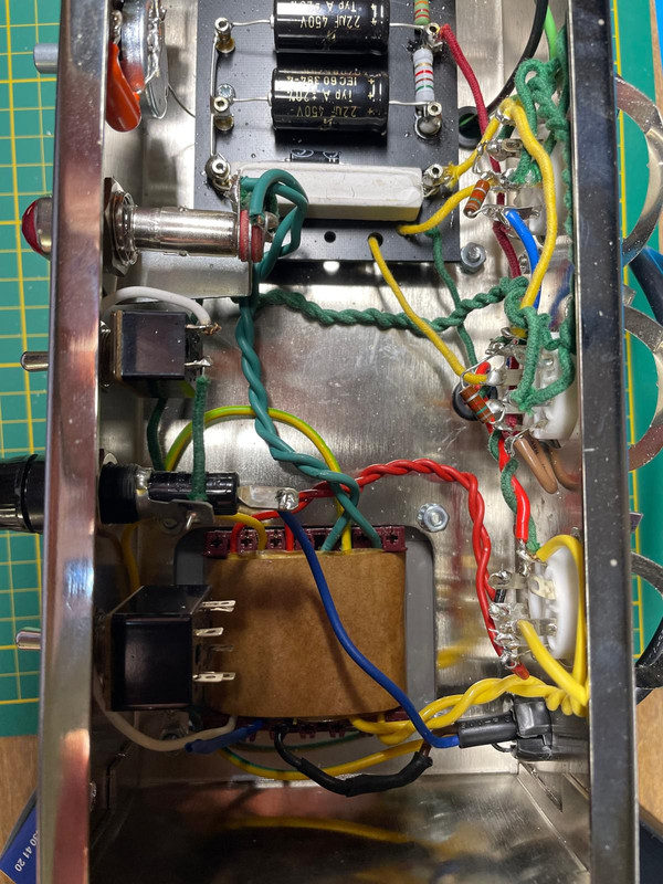
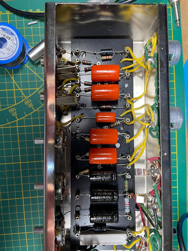
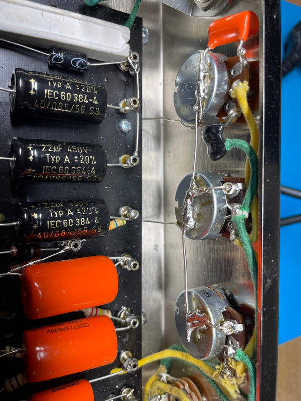
Below are updated pictures of the works for your approval. The dull solder here and there is not from cold joints but I suspect from mixing copper, lead and tin.
As for the sound, there is now. It's just not loud. Rather quiet actually. Library volume.
The preamp tubes show no glow. I tested the filament and got a perfect 6.5V without tubes or 5.2V with tubes installed (is that voltage drop normal?). Pot 1 is mostly unresponsive. Tone doesn't seem to be doing much of anything either, but it's hard to tell.
Bigges problem, methinks, is the voltage on B1. My multimeter does something completely new there. It switches continuously between 123.12 and 12.312. I'm not sure what it's trying to tell me. I don't suspect these are actual voltage modulations.
That's where I called it a day. Tomorrow I have an appointment with an upholsterer for my cabinet. I won't even attempt doing that myself. A man has to know his limitations.
Not sure when my next round will be, but any of your wisdom in matters of the current status will be greatly appreciated as always.
Meanwhile I did follow your advise, read up on proper turret soldering and invested in a 5mm chissel tip and a role of 60/40. I have to admit that the right tip and solder makes all the difference. I'm fine with using silver for PCB soldering, but I will neverever use it on turrets again.
Below are updated pictures of the works for your approval. The dull solder here and there is not from cold joints but I suspect from mixing copper, lead and tin.
As for the sound, there is now. It's just not loud. Rather quiet actually. Library volume.
The preamp tubes show no glow. I tested the filament and got a perfect 6.5V without tubes or 5.2V with tubes installed (is that voltage drop normal?). Pot 1 is mostly unresponsive. Tone doesn't seem to be doing much of anything either, but it's hard to tell.
Bigges problem, methinks, is the voltage on B1. My multimeter does something completely new there. It switches continuously between 123.12 and 12.312. I'm not sure what it's trying to tell me. I don't suspect these are actual voltage modulations.
That's where I called it a day. Tomorrow I have an appointment with an upholsterer for my cabinet. I won't even attempt doing that myself. A man has to know his limitations.
Not sure when my next round will be, but any of your wisdom in matters of the current status will be greatly appreciated as always.
-
Stevem
- Posts: 4984
- Joined: Fri Jan 24, 2014 3:01 pm
- Location: 1/3rd the way out one of the arms of the Milkyway.
Re: 5E3 - First build, first dud
With no tubes in the amp when you read across pins 2 and 7 on either output tube you should read well over 7 volts.
With all the tubes in the amp you should not read less then 6.1 vac.
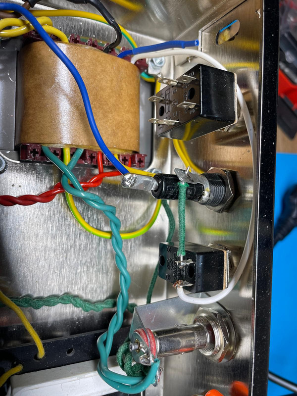
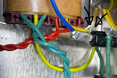
I can’t tell from your pictures, but where is that green / yellow wire from the secondary of the power transformer going?
It should be bolted or soldered to the chassis to get its needed ground connection if it’s the center tap of the 6.3 volt filament winding.
With all the tubes in the amp you should not read less then 6.1 vac.
I can’t tell from your pictures, but where is that green / yellow wire from the secondary of the power transformer going?
It should be bolted or soldered to the chassis to get its needed ground connection if it’s the center tap of the 6.3 volt filament winding.
When I die, I want to go like my Grandfather did, peacefully in his sleep.
Not screaming like the passengers in his car!
Cutting out a man's tongue does not mean he’s a liar, but it does show that you fear the truth he might speak about you!
Not screaming like the passengers in his car!
Cutting out a man's tongue does not mean he’s a liar, but it does show that you fear the truth he might speak about you!
-
FrankTheReverbTank
- Posts: 10
- Joined: Sun Mar 16, 2025 10:07 pm
Re: 5E3 - First build, first dud
Why would I have 7 volts on the filament? The trafo only delivers 6.3V.Stevem wrote: ↑Mon Jun 02, 2025 7:54 pm With no tubes in the amp when you read across pins 2 and 7 on either output tube you should read well over 7 volts.
With all the tubes in the amp you should not read less then 6.1 vac.
I can’t tell from your pictures, but where is that green / yellow wire from the secondary of the power transformer going?
It should be bolted or soldered to the chassis to get its needed ground connection if it’s the center tap of the 6.3 volt filament winding.
It is grounded. It's lugged to the transformerfoot/chassis just behind the fuse.
Re: 5E3 - First build, first dud
You typically get a higher voltage when tubes aren't pulling any current.FrankTheReverbTank wrote: ↑Mon Jun 02, 2025 8:56 pm Why would I have 7 volts on the filament? The trafo only delivers 6.3V.
Check the blue plate wire, doesn't look like it's connected well. Next to it is the screen, looks like you have the 1k5 grid stopper going to the screen grid instead of the control grid.
Edit: never mind, camera trick. Solder joint on the grid does look kinda iffy.
-
Stevem
- Posts: 4984
- Joined: Fri Jan 24, 2014 3:01 pm
- Location: 1/3rd the way out one of the arms of the Milkyway.
Re: 5E3 - First build, first dud
For the any transformer to deliver 6.3 volts for the heaters with all the tubes in it will deliver well over 6.3 volts with no tubes in due to that winding being unloaded.
As I type this I am working on a Fender Bandmaster and with no tubes in it’s got 6.8 volts showing up.
So that’s almost 10% regulation which is typical.
As I type this I am working on a Fender Bandmaster and with no tubes in it’s got 6.8 volts showing up.
So that’s almost 10% regulation which is typical.
When I die, I want to go like my Grandfather did, peacefully in his sleep.
Not screaming like the passengers in his car!
Cutting out a man's tongue does not mean he’s a liar, but it does show that you fear the truth he might speak about you!
Not screaming like the passengers in his car!
Cutting out a man's tongue does not mean he’s a liar, but it does show that you fear the truth he might speak about you!
-
Stevem
- Posts: 4984
- Joined: Fri Jan 24, 2014 3:01 pm
- Location: 1/3rd the way out one of the arms of the Milkyway.
Re: 5E3 - First build, first dud
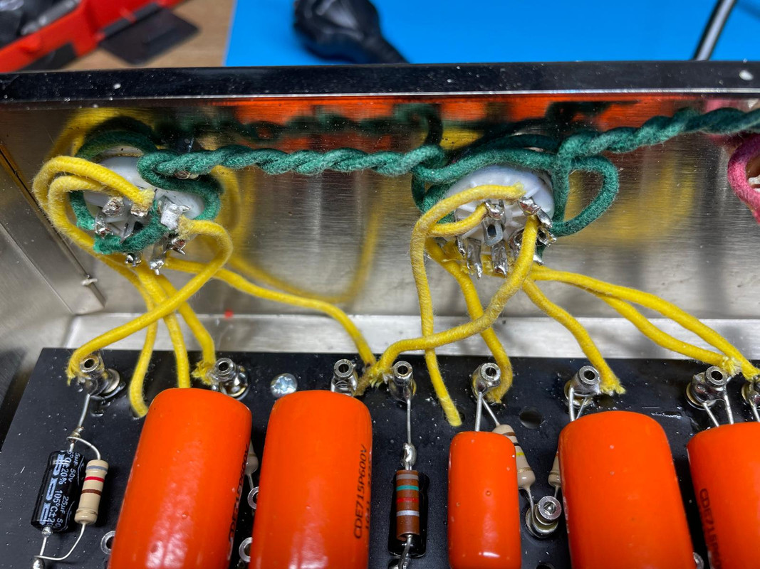
Are you using two shorting type speaker jacks it looks like.
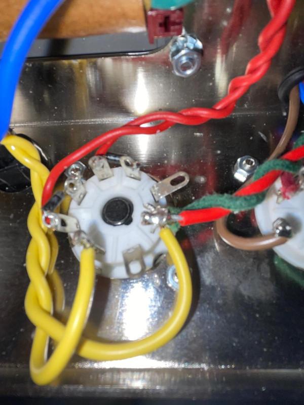
Also as someone mentioned your output tube socket wiring does not look right from what I can make out.
Can you take more of a downward photo of them instead of a sideways?
That would be really helpful for us.
Also as someone mentioned your output tube socket wiring does not look right from what I can make out.
Can you take more of a downward photo of them instead of a sideways?
That would be really helpful for us.
When I die, I want to go like my Grandfather did, peacefully in his sleep.
Not screaming like the passengers in his car!
Cutting out a man's tongue does not mean he’s a liar, but it does show that you fear the truth he might speak about you!
Not screaming like the passengers in his car!
Cutting out a man's tongue does not mean he’s a liar, but it does show that you fear the truth he might speak about you!
-
johnnyreece

- Posts: 1061
- Joined: Thu Jan 26, 2012 2:05 am
- Location: New Castle, IN
Re: 5E3 - First build, first dud
That's a whole lot of drop on the filament winding...If it were me, I'd try inserting the tubes one by one, or at least in groups (for example, preamp first, then power), and measuring the voltage to try and narrow down where that drop is coming from. I know you have multiple problems to chew on, so take my opinion with a grain of salt.
Re: 5E3 - First build, first dud
If it's stuck between those numbers it could be an error. What kind of meter do you have? Is it auto ranging? If not, you want to be in the 500VDC setting or whatever the highest DC voltage setting your meter has to measure the B+ nodes. Cathodes should be around 1 or 2VDC on the preamp tubes, around 18v on the power tubes, so you want your meter in a lower voltage setting. If your amp were really doing this you would hear it. Have you measured other voltages? Sharing a list of DC voltages on the plate, grid(s), and cathode of each tube would be helpful to track down the issue.FrankTheReverbTank wrote: ↑Mon Jun 02, 2025 7:37 pm Bigges problem, methinks, is the voltage on B1. My multimeter does something completely new there. It switches continuously between 123.12 and 12.312. I'm not sure what it's trying to tell me. I don't suspect these are actual voltage modulations.
-
FrankTheReverbTank
- Posts: 10
- Joined: Sun Mar 16, 2025 10:07 pm
Re: 5E3 - First build, first dud
The kit came with only one type of jack. The shortening type.Stevem wrote: ↑Mon Jun 02, 2025 11:08 pm Are you using two shorting type speaker jacks it looks like.
Also as someone mentioned your output tube socket wiring does not look right from what I can make out.
Can you take more of a downward photo of them instead of a sideways?
That would be really helpful for us.
(It also came with one type of noval socket. The wrong type)
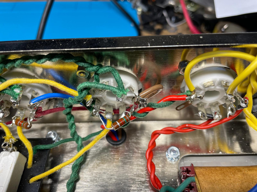
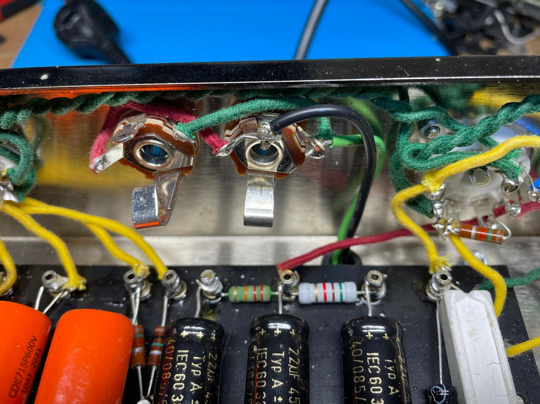
Hope these will do. My phone isn't too happy with little distance and lots of flash.
Re: 5E3 - First build, first dud
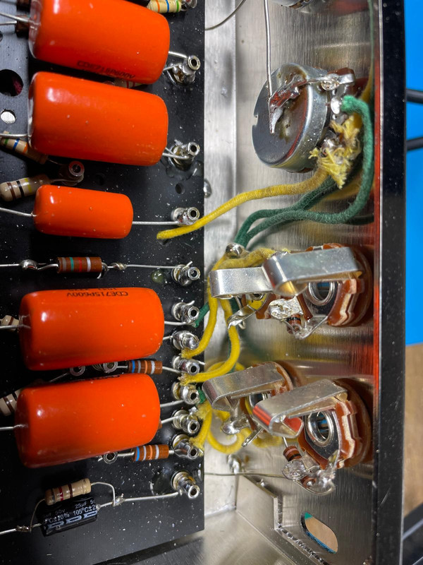
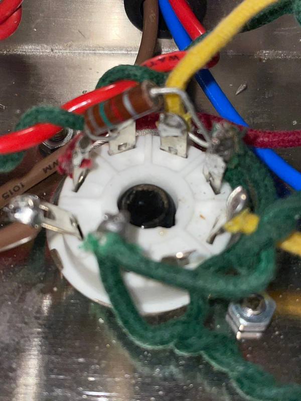
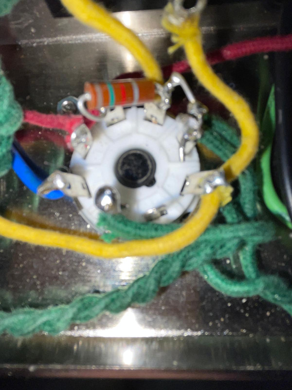
None of the pins on the output tube sockets should be touching each other. That resistor shouldn't come close to touching anything but the two pins it is connected to.
-
Stevem
- Posts: 4984
- Joined: Fri Jan 24, 2014 3:01 pm
- Location: 1/3rd the way out one of the arms of the Milkyway.
Re: 5E3 - First build, first dud
It’s still hard to tell, but in that last photograph of the output tube socket it looks like pin 6 side of that 1.5k resistor is touching pin 7.
When I die, I want to go like my Grandfather did, peacefully in his sleep.
Not screaming like the passengers in his car!
Cutting out a man's tongue does not mean he’s a liar, but it does show that you fear the truth he might speak about you!
Not screaming like the passengers in his car!
Cutting out a man's tongue does not mean he’s a liar, but it does show that you fear the truth he might speak about you!
-
FrankTheReverbTank
- Posts: 10
- Joined: Sun Mar 16, 2025 10:07 pm
Re: 5E3 - First build, first dud
Don't know what got into me there. Think it was one of Rob Robinette's wiring diagrams with a lead color that didn't come out clearly from my printer, bad basement lighting and... oh yea, color blindness. Anyway, I intentionally wired the resistor leg on pins 6 and 7.
I was sure you nailed the issue there since I essentially placed a resistor on the filament. So I played hooky for an hour and fixed it in full anticipation of a sound hurricane.
Sadly it only made a minor difference. Little bit louder and the tone is working now.