My first build: 18w TMB

General discussion area for tube amps.

Moderators: pompeiisneaks, Colossal

Mono243
Posts: 19
Joined: Thu Jun 24, 2010 10:54 pm

My first build: 18w TMB

Post by Mono243 »

Hi guys... I'm new here so be nice :)

Decided that building amps would be more rewarding than buying them and heck, I might even learn something on the way. The Marshall 18w circuit seemed a good place to start (as I don't like the sound of low-watt Fender circuits).

I have no previous experience of amp building and the only resource I used were these layouts from Trinity and Ceriatone:

http://www.trinityamps.com/ForumGallery ... _21Dec.jpg
http://www.ceriatone.com/images/layoutP ... iatone.jpg

I'm going to write this up from a newcomer's perspective, so apologies in advance for the really basic explanation. I hope future builders can learn from my mistakes and avoid them in their own projects.

Here goes...
Mono243
Posts: 19
Joined: Thu Jun 24, 2010 10:54 pm

Re: My first build: 18w TMB

Post by Mono243 »

So, this is basically just a lot of soldering and wire bending. A lot.
I expected to be able to understand what made a tube amp tick by the end of this, but really, I don't. Maybe one day, but this project was really just an exercise in planning and spacial awareness...

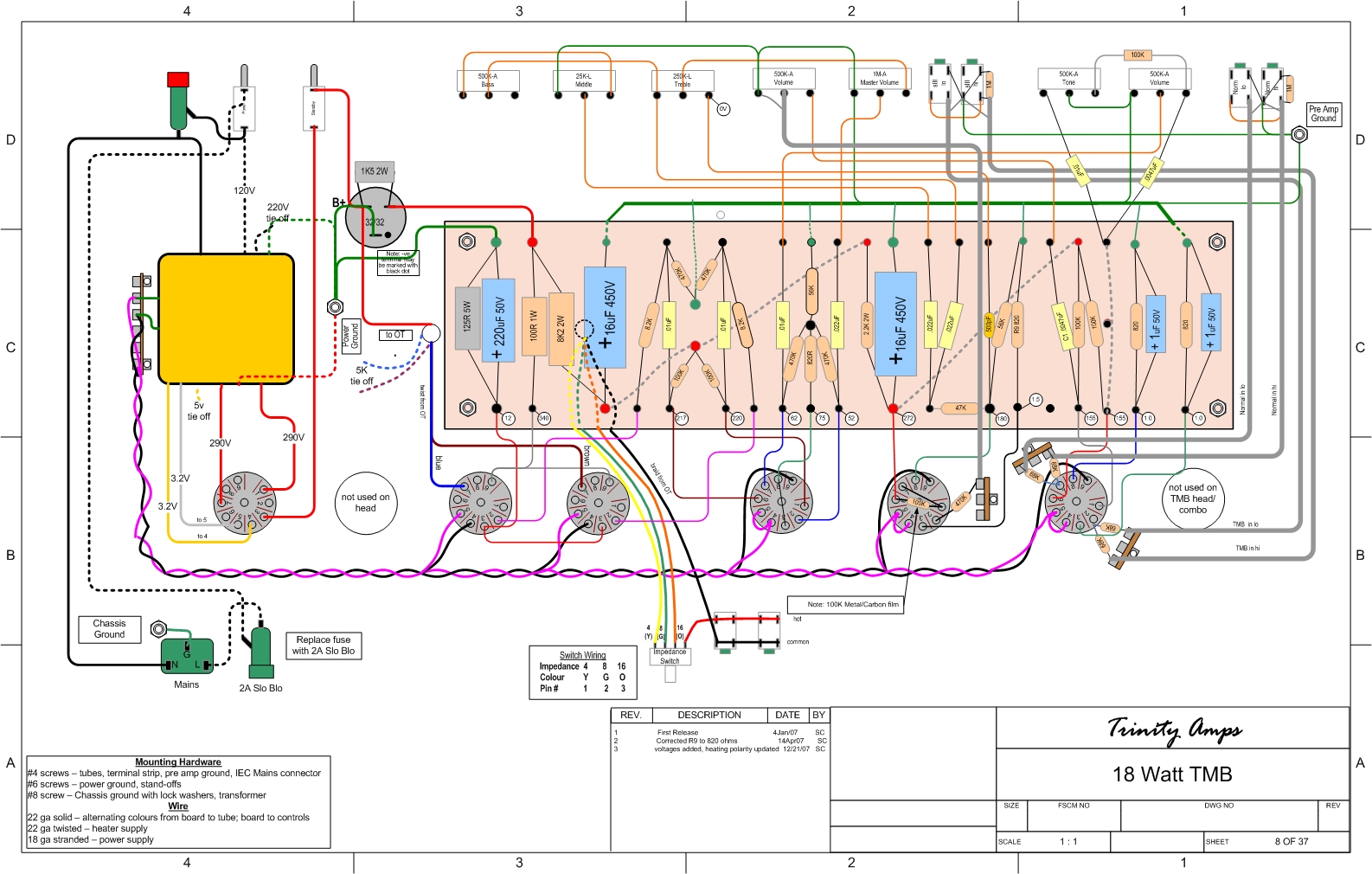
Anyway, after studying the layout for a number of days, I made my own parts list. As my parts arrived, I ended up with loads of bags of resistors, caps, wire, etc etc etc... The first thing I wanted to do was get my feet wet by wiring up the turretboard...

The tools I used throughout this project are as follows:

[img:640:480]http://i1003.photobucket.com/albums/af1 ... C02830.jpg[/img]

A variety of pliers (small, medium, large), wire strippers (variable), wire cutters, dental mirror, scissors, various screwdrivers, soldering iron, monkey wrench, knife. Small cable ties are also VERY handy. I can't emphasise how important the right tools for the job are. If you regularly fiddle about with electronics or your guitar, it's handy to have your own tools and they last forever (usually!)...

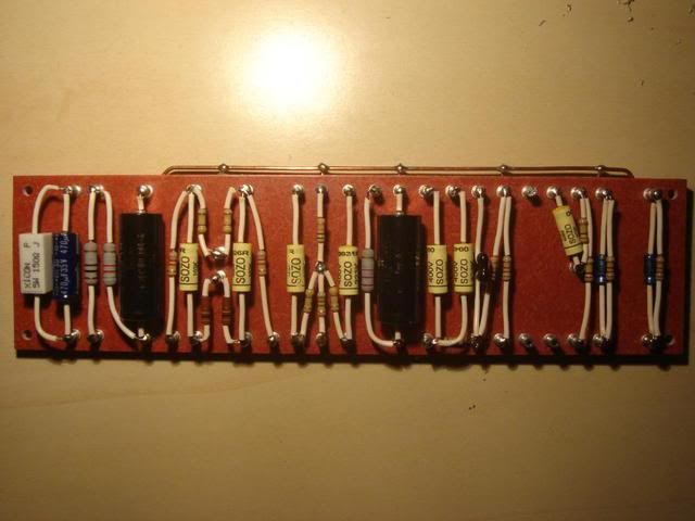
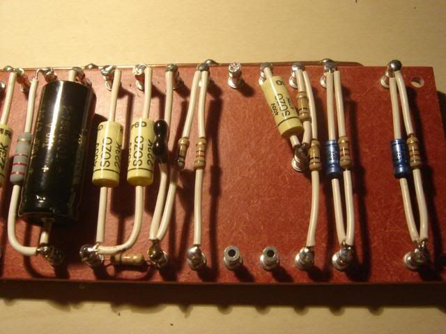
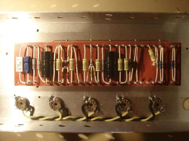
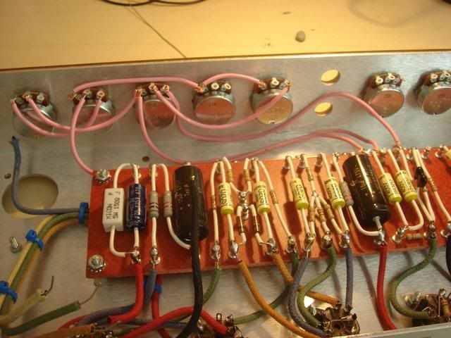
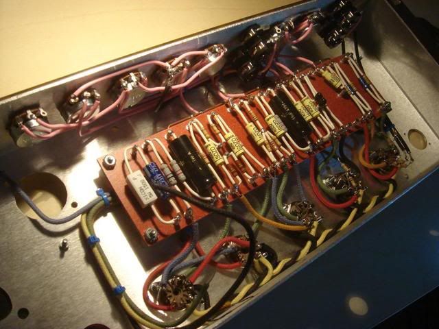
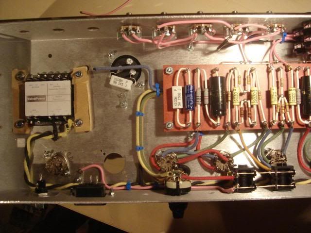
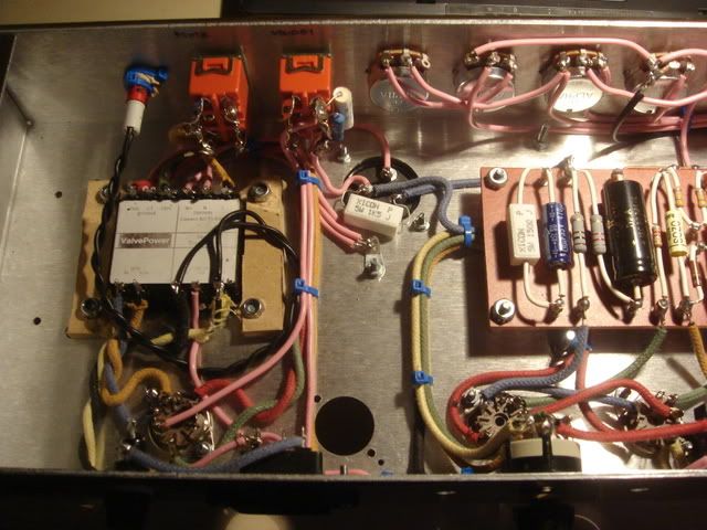
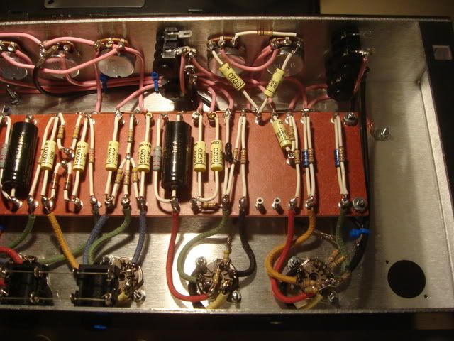
Here is the turretboard wired up and soldered:

[img:640:480]http://i1003.photobucket.com/albums/af1 ... C02765.jpg[/img]

The white stuff along the wires is PVC tubing of 1mm diameter, which (in my head) will limit the amount of noise induced into the circuit. Not necessary but whatever, it was really cheap.

Important parts:
1. Assemble the turretboard "dry" first off. Don't solder until you are happy with where everything should be going and connecting.
2. Make as many "dry" connections to a point as you can anticipate before you try to solder. This holds true throughout the build, as de-soldering is tricky and I often ended up burning my fingers (not good).
3. When bending leads, appreciate how the weight of the component will sit it between the points.
4. It is important that a solder joint is mechanically strong and holds, even before it is soldered... this ensures the joints longevity.

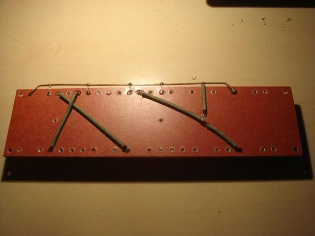
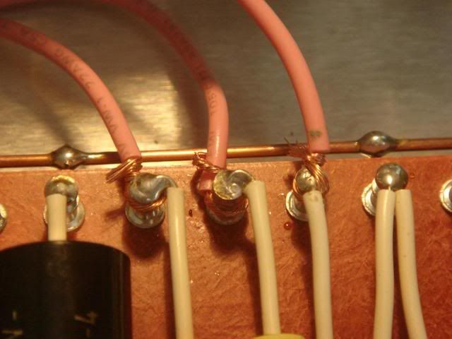
Some people might not know this, so for their sake: the copper wire along the top of the turretboard (TB) fits into holes on the underside of it that are also parts of the turrets. It acts as a common ground point which will eventually go to Earth.
Mono243
Posts: 19
Joined: Thu Jun 24, 2010 10:54 pm

Re: My first build: 18w TMB

Post by Mono243 »

On closer inspection of the TB wiring, we can see that there are many small bends that need to be made in the wires so as to fit the components comfortably. Check out the small resistor with bare leads at the bottom...

[img:640:480]http://i1003.photobucket.com/albums/af1 ... C02767.jpg[/img]

To manipulate the leads like that without breaking them away from the component, I use the small pliers (blue handles) right against the component and then bend the lead. Difficult to describe, but with patience you can have leads navigate very complicated paths and looking semi-decent.

This is the back of the turretboard:

[img:640:480]http://i1003.photobucket.com/albums/af1 ... C02768.jpg[/img]

You have to use your brain a bit to mirror the wiring seen on the layout (http://www.trinityamps.com/ForumGallery ... _21Dec.jpg) but it does make sense. Also, this was my first ever dealing with the thick 20awg cloth-covered wire that I ordered. This stuff is TOUGH, but it stays in shape. The hardest part about using it was adjusting the variable wire strippers to cut through the cloth but not damage the solid core. I got the hang of it after a while and really like the feel of it too.
Mono243
Posts: 19
Joined: Thu Jun 24, 2010 10:54 pm

Re: My first build: 18w TMB

Post by Mono243 »

And now to the chassis. This seemed pretty large when I first got it, but incredibly it almost seems smaller as more and more wiring goes into it. The first logical thing I could think to do with it was install the tube sockets. These are all 9-pin sockets, as that is what the tube compliment of this circuit (EZ81 rectifier, 2x EL84 power, 3x 12AX7 pre) fit into...

[img:640:480]http://i1003.photobucket.com/albums/af1 ... C02769.jpg[/img]

The screws I had bought for this were M3 size (3mm diameter), but the holes in the chassis were too small. Because I had been waiting so long to get this done, I couldn't be bothered to order new screws in a smaller size, so I went at it with my Dad's powerdrill. A few seconds later, and my M3 screws fitted perfectly

The big holes in the chassis on the left are for the power transformer (PT) and cap-can. The two screws above the tube socket second from the left are to hold in the output transformer (OT) but I hadn't attached it at this point.

I have a book on Tube Amps by Gerald Weber, but honestly I find it almost unreadable. The one piece of information I have managed to gleam from it would be that the tube heater wiring should go into the chassis first...

[img:640:480]http://i1003.photobucket.com/albums/af1 ... C02770.jpg[/img]

Ok, so this bit is kind of tricky. My best advice would be to study the layout quite hard, work out where your pins are on each tube and think about what you have to do. As you can see on the layout:
pins 4, 5 and 9 are used on the preamp tubes
pins 4 and 5 are used on the power tubes
and don't worry about the rectifier tube (EZ81) just yet
Mono243
Posts: 19
Joined: Thu Jun 24, 2010 10:54 pm

Re: My first build: 18w TMB

Post by Mono243 »

It is important to cut the wire lengths long enough so you can wrap them comfortably around the socket pins. In fact, make them too long and then trim them back to guarantee a good solder joint.

When wiring the preamp tubes, notice that they are wired in series. This means that apart from the first one (furthest on the right), each preamp tube will have 2 connections to it's heater pins (4, 5 and 9), so that they are attached to the tubes on either side of them. The layout isn't particularly clear on this point and I had to work it out for myself, but there is basically one big heater circuit connecting all of the tubes together.

This means that you have to squeeze a lot of connections onto each tiny pin:

[img:640:480]http://i1003.photobucket.com/albums/af1 ... C02771.jpg[/img]

In this photo you can see that there are two connections to each pin, bent back on themselves for stability. Because of this delicate operation and handling of the heater wire, it is important to get this circuit down first.

Important parts:
1. The heater circuit wire (yellow and black) are twisted so as to minimise noise induction into the circuit. Nobody has really offered me a clear explanation of this yet (hopefully somone in this thread will) but I have heard whisperings of phase cancellation/humbucking etc. Who knows?!
2. Anticipating the twists/lengths of wire to fit comfortably between two sockets takes a bit of experience. If I have learnt one thing from this project it is to over-order any wire you use, because it goes, really fast! You can never have too much, and you can always use it in different projects.
3. I first tried twisting the wire by attaching two to a fixed point and fixing their ends into my power drill and turning them slowly. This method seems to work for PVC/thin wire, but doesn't work well at all for cloth-covered wire and actually ripped some of the cloth. Don't try it at home kids! All twisted wire in this project was done by hand, holding the expected lengths in the large pliers (orange handles) and twisting at 45 degrees with my free hand.
4. The small pliers (blue handles) were my main tool for the entire project. I used them to bend sharp corners in leads and wires almost every minute and were particularly used in picking up small bits that I dropped into the chassis as I worked

So, what you should end up with is short (2 inch) sections of twisted wire between each tube socket. I'm a bit of a perfectionist, so I worked to have mine end up looking like a continuous filament across the bottom of the chassis, where similar wires in the circuit would overlap each other:

[img:640:480]http://i1003.photobucket.com/albums/af1 ... C02774.jpg[/img]

This was probably the 2nd hardest part of the build and something I would recommend taking time and care over, because tubes don't work without being heated
Mono243
Posts: 19
Joined: Thu Jun 24, 2010 10:54 pm

Re: My first build: 18w TMB

Post by Mono243 »

So this is what I ended up with:

[img:640:480]http://i1003.photobucket.com/albums/af1 ... C02775.jpg[/img]

I'll take this opportunity to make an important observation, which I did not fully appreciate at the time.

Amps are built in a series of layers effectively, with wires sitting on the floor of the chassis, under the turretboard, from the turretboard to the floor, and on higher levels to the potentiometers and such. In order to save yourself a lot of hassle and delicate/difficult soldering in the future, I would recommend building upwards, from the lowest/floor level up to those much more exposed and accessible.

When I reached this point in the build, I stupidly attached the turretboard to the chassis by the 4 nuts and started wiring on a higher level than I should have (from turretboard to tube socket pins). If you look on the layout (http://www.trinityamps.com/ForumGallery ... _21Dec.jpg) you can see wires that pass from the outside of the chassis (from the Output Transformer) through two holes underneath the turretboard. Before you screw the turretboard in, put wire through these two holes in sufficient length to reach the Ohm selector, can cap and power tubes. It might also be worth soldering the jack inputs at this point and passing the coaxial cable across the floor of the chassis, as I found this hard to do with the turretboard already in place.

Anyway, let's continue with the hard way, which I would not recommend!

[img:640:480]http://i1003.photobucket.com/albums/af1 ... C02781.jpg[/img]

As you can see, I have continued the heater wiring with enough length to comfortably reach the power transformer, and also made the necessary connections between the lower side of the turretboard and the tube sockets. When I was soldering to the pins, I made sure that the wires avoided the nuts holding the sockets in, as I had yet to attach the tube shields and retaining springs to the outside of the chassis, and without clear access to the nuts on the inside, it would be very tricky.
Mono243
Posts: 19
Joined: Thu Jun 24, 2010 10:54 pm

Re: My first build: 18w TMB

Post by Mono243 »

It was at this point that I realised the turretboard had been put in place too early!
I unscrewed it and carefully lifted it so I could access the holes underneath it. Fortunately, the cloth-covered wire proved to be pretty resilient and most of my solder joints betweent the turretboard and tube socket pins held, only about 4 broke but they are quite easily fixed.

[img:640:480]http://i1003.photobucket.com/albums/af1 ... C02790.jpg[/img]

I decided to overestimate the length of wire needed between the OT and the Ohms selector/can cap/power tubes as I didn't want to go back under there...

It's also important to leave enough wire on the outside of the chassis to reach the terminals on the OT (which should be facing towards the PT). I started using the cable ties at this point to hold the bundles of wire together.

[img:640:480]http://i1003.photobucket.com/albums/af1 ... C02792.jpg[/img]
Mono243
Posts: 19
Joined: Thu Jun 24, 2010 10:54 pm

Re: My first build: 18w TMB

Post by Mono243 »

After a few hours of stressful and cramped soldering, I relaxed by putting the jacks together. A useful tip I picked up is that you can set them up on the outside of the chassis (the same distance apart) to do this, and it sure makes life easier...

[IMG:640:480]http://i1003.photobucket.com/albums/af1 ... C02798.jpg[/img]

I also took my time off to install the fuse-holder and IEC power socket.
The powersocket fit perfectly, but the fuse-holder was slightly too small for the hole already drilled in my chassis. I fixed this by using the "On/Off" washer that came with my Power/Standby switches as a washer for the fuse-holder, and it holds it perfectly in place:

[IMG:640:480]http://i1003.photobucket.com/albums/af1 ... C02801.jpg[/img]
Mono243
Posts: 19
Joined: Thu Jun 24, 2010 10:54 pm

Re: My first build: 18w TMB

Post by Mono243 »

The pots were the next things to do. I realised that I wouldn't have enough cloth-covered wire to finish the amp with, and that even if I did, it would also be difficult to wire the front of the amp with it, as it is a much more confined space. I ordered some PVC stranded copper wire and this was ideal for the job.

[IMG:640:480]http://i1003.photobucket.com/albums/af1 ... C02803.jpg[/img]

I could have mounted the pots on the outside and wired them in the same way that I did the jacks, but this way wasn't too tricky. As with the rest of the amp, if you want a neat build, it is important to wire in layers. Look at the layout, establish what are the deepest and shallowest wires and go from back to front.

This was the first point at which wire spacing became in issue. The jacks (and their associated wiring) are actually fairly large and in order to have the pots-to-turretboard wires pass beneath them comfortably, they had to be fairly compact. It's also good to have a wider perspective on what wires pass near/over those you are doing at the moment and try and incorporate them if you are using cable ties:

[IMG:640:480]http://i1003.photobucket.com/albums/af1 ... C02805.jpg[/img]
Mono243
Posts: 19
Joined: Thu Jun 24, 2010 10:54 pm

Re: My first build: 18w TMB

Post by Mono243 »

Just a quick word about attaching wires to the turretboard from other sources...

On each turret, there is a hole at the top beneath which is a narrowing in the metal. The idea is that wires are either bent to sit in the hole at the top (and are then soldered in place), or wrapped around the wiring and soldered into place (but this can often get messy).

In my opinion, the "best way" to attach wires to the turretboard differes depending on whether you are using solid-core or stranded wire.

Solid-core Wire:
Leave the turretboard "dry" for as long as possible and avoid soldering anything in place (this means you have to be very delicate when handling it). When you need to attach a wire to the turretboard from another source, bend it to a 90 degree angle and sit it in the hole at the top of the turret, as you did for the components sitting on the turretboard.

I did not know to do this for my build, but instead I used the method for stranded wire throughout (even with my solid-core cloth-covered wire).

Stranded Wire:
Once the plastic/PVC sheathing is stripped away to a fair distance (1 inch), twist the exposed copper around itself tightly with your fingers. Put a 90 degree bend in this and work it around the narrowing in the turret metal. Once the wire core is around this, twist it back on itself to secure it in place, like so:

[IMG:640:480]http://i1003.photobucket.com/albums/af1 ... C02804.jpg[/img]

This method does tend to be a bit messy and I for one will often overdo it on the solder.
For my next build I will endeavour to use a smaller gauge solid-wire throughout and let you know how it goes.

Either way, this is where we are up to:

[IMG:640:480]http://i1003.photobucket.com/albums/af1 ... C02809.jpg[/img]

Done so far:

Turretboard component wiring
Tube heater wiring
Turretboard to tube sockets wiring
OT wiring
Potentiometer and Jack wiring (including coaxial cables to tube sockets) except connections to Earth

Probably spent around 6 hours on it up to this point.
Mono243
Posts: 19
Joined: Thu Jun 24, 2010 10:54 pm

Re: My first build: 18w TMB

Post by Mono243 »

Ok, now comes the time for the most frustrating and irritating part of my build. Being the stubborn bastard that I am, I ordered my chassis and transformers from different sources. Well, (and I probably deserved this) the Output Transformer (OT) fit just fine, but the Power Transformer's attachment screws were too close together compared to those already drilled into the chassis!

The worst part was that I couldn't even drill new holes in the chassis, as their ability to hold up the PT would be compromised by the proximity of the old holes. Hard to describe and I am by no means an engineer...

This isn't relative to the build, I realise, but I am proud of my own work-around. I got out a rusty file and started going at the PT cavity to widen it so that it could accomodate all 4 of my PT's attachment nuts:

[IMG:640:480]http://i1003.photobucket.com/albums/af1 ... C02787.jpg[/img]

Not a very professional job, I know but it gets even better!
My next bright idea was to make some "holds" for the attachment nuts. Metal would have been the best candidate material for the job, but while I wait for my friend to help me make such a thing, I reckon I can get by with good old MDF fibreboard...

[IMG:640:480]http://i1003.photobucket.com/albums/af1 ... C02811.jpg[/img]

I put one of these on each side and screwed them in. Not very pretty really, but I don't plan on chucking this amp around anytime soon so I reckon they will hold until I have a better replacement.

It's looking pretty ghetto so far
Mono243
Posts: 19
Joined: Thu Jun 24, 2010 10:54 pm

Re: My first build: 18w TMB

Post by Mono243 »

After this I attached the OT to the outside of the chassis. No such problems here

[IMG:640:480]http://i1003.photobucket.com/albums/af1 ... C02814.jpg[/img]

The textbook was used to prop the amp up at different angles to make soldering in tight corners much easier. I would recommend thinking about the easiest way to achieve something that seems difficult, rather than going at it for half an hour and getting nowhere except frustration.

I then went on to screw in the ground lugs (which provide an Earth connection), the cap can, and wire up the Ohm selector and output jacks that follow it (yellow, green and orange wires go through to the OT, pink wire goes to ground lug).

[IMG:640:480]http://i1003.photobucket.com/albums/af1 ... C02820.jpg[/img]
Mono243
Posts: 19
Joined: Thu Jun 24, 2010 10:54 pm

Re: My first build: 18w TMB

Post by Mono243 »

The next bit I don't remember too well (I was doing it last night at around 4am) but it was quite stressfull. I had decided to be as neat as possible and wanted to wire the rectifier tube and PT so that any wires going in the same direction could be cable tied together. What started as a mess...

[IMG:640:480]http://i1003.photobucket.com/albums/af1 ... C02824.jpg[/img]

... ended up looking pretty decent...

[IMG:640:480]http://i1003.photobucket.com/albums/af1 ... 2831-1.jpg[/img]

As previously mentioned, I am a perfectionist
The wiring of the PT is not as complicated as it first looks, and the Ceriatone layout explains it much better than the Trinity one.

There is also something I would like to ask the experts about:
I sent a 0v and 6.3v tap to pins 4 and 5 of the rectifier tube respectively, as indicated in the Ceriatone layout (http://www.ceriatone.com/images/layoutP ... iatone.jpg), whereas the Trinity layout which I had been following said it should be 3.5v to each of these pins... Should I change the wiring or are these the same thing effectively??
Mono243
Posts: 19
Joined: Thu Jun 24, 2010 10:54 pm

Re: My first build: 18w TMB

Post by Mono243 »

After this I installed the valve retainers and shields on the outside of the chassis:

[IMG:640:480]http://i1003.photobucket.com/albums/af1 ... C02819.jpg[/img]

I sealed the nuts and bolts on the inside using clear nail varnish, as this will stop them from vibrating free as I play the amp.
It is also interesting to know that the height of the OT and PT means that the amp can be sat upside down without damaging any of the retainers springs or tube shields.

Here is what the inside looks like as of now:

[IMG:640:480]http://i1003.photobucket.com/albums/af1 ... C02833.jpg[/img][IMG:640:480]http://i1003.photobucket.com/albums/af1 ... C02834.jpg[/img]

In the first picture, note that I have wired up the pilot light and the Power and Standby switches.
I used an elastic band and pressure from cable ties to hold the pilot light in a hole that was slightly too large for it (works perfectly) and with the switches, I spent ages manipulating the leads to follow complicated paths, as this is a very cramped area with a lot of components.

In the second picture, notice the resistors across the tube sockets and the coaxial cable coming from the inputs on the front of the chassis. These are quite difficult to solder (resistors are delicate, spindly things) and I would suggest doing them at the very start, before the tube socket wiring proper and turretboard are in place.
Mono243
Posts: 19
Joined: Thu Jun 24, 2010 10:54 pm

Re: My first build: 18w TMB

Post by Mono243 »

That's as far as I have got folks, probably about 90% done.
Tomorrow I'm going to go over the layout and compare it with my own circuit, one solder joint at a time and make sure everything is looking good. I don't have a cable yet to plug it into my cabinet (25w Greenback, yummy!) but it is on the way. I can't test it out until it gets here so I might as well spend the time making sure it's put together right!!

Comments, criticism, questions... let me know :)
Post Reply