I usually set up my Marshall builds with the main filter stack on the rectifier side of the SB switch. But this high-voltage JTM100 amp I'm building will have the screen supply taken from the middle of that main filter stack (i.e. - B+/2). So if don't change anything there would be B+/2 on the screens in Standby. I don't know if that is even a problem but I thought I should try to think of easy ways to avoid it.
I decided the easiest way to fix that is to just do it the way Marshall originally did, put the SB between the rectifier and the main filter stack.
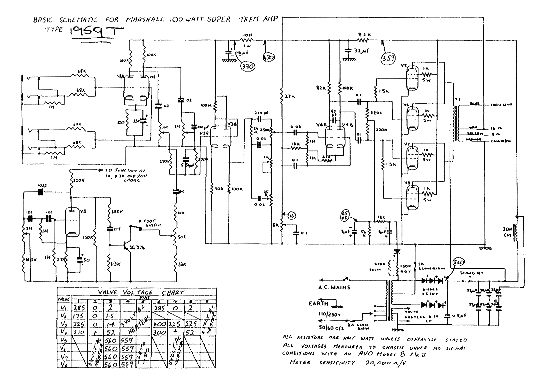
So that left me looking to see if I needed a snubber cap on the rectifiers. I noticed in the old 1966 Super Trem schematic there was a 0.05uF cap from recitfier out to ground. This is a FW CT rectifier not the FW bridge you see on post-1966 Marshalls. I'll be using 4x UF5408. But that cap to ground sort of looks like a 'death cap' to me. I've read a little about safety caps and the difference between X and Y rated caps. I have a PP 47n/2kv cap but it doesn't look like it's safety rated. Looking on Mouser/Digikey, the safety rated caps at high voltage look like snap-in legos.
Would putting this cap across the SB switch be preferable? Effective? Would adding a series 100R/2W resistor improve the snubber?
Here is the '66 Super Trem schematic (JTM100 with Tremolo). I'll be adding balance resistors in parallel with those filter stacks. The PT HTCT will be fused as-in this schematic.
Early brewers were primarily women, mostly because it was deemed a woman's job. Mesopotamian men, of some 3,800 years ago, were obviously complete assclowns and had yet to realize the pleasure of brewing beer.
jbrew73 wrote: ↑Sun Jul 19, 2026 11:21 am
Are you using a full wave ct or full wave bridge on your amp?
Just like that schematic except 4x UF5408 diodes. Not bridge.
Early brewers were primarily women, mostly because it was deemed a woman's job. Mesopotamian men, of some 3,800 years ago, were obviously complete assclowns and had yet to realize the pleasure of brewing beer.
Can you tap the screen supply from the stacked cap center point on a fwct supply?
I don’t think that I have ever seen that. I have only seen it on a fwb supply where the transformer ct is used to keep the capacitor center point at 1/2 voltage.
jbrew73 wrote: ↑Sun Jul 19, 2026 12:47 pm
Can you tap the screen supply from the stacked cap center point on a fwct supply?
I don’t think that I have ever seen that. I have only seen it on a fwb supply where the transformer ct is used to keep the capacitor center point at 1/2 voltage.
There will be balancing resistors in parallel with the stack. I think it should be that way anyway. Like in a Fender first cap.
Early brewers were primarily women, mostly because it was deemed a woman's job. Mesopotamian men, of some 3,800 years ago, were obviously complete assclowns and had yet to realize the pleasure of brewing beer.
Fischerman wrote: ↑Sun Jul 19, 2026 11:15 am
I usually set up my Marshall builds with the main filter stack on the rectifier side of the SB switch. But this high-voltage JTM100 amp I'm building will have the screen supply taken from the middle of that main filter stack (i.e. - B+/2). So if don't change anything there would be B+/2 on the screens in Standby. I don't know if that is even a problem ...
Definitely a problem.
Without plate supply the screen becomes the anode causing excessive screen current and dissipation.
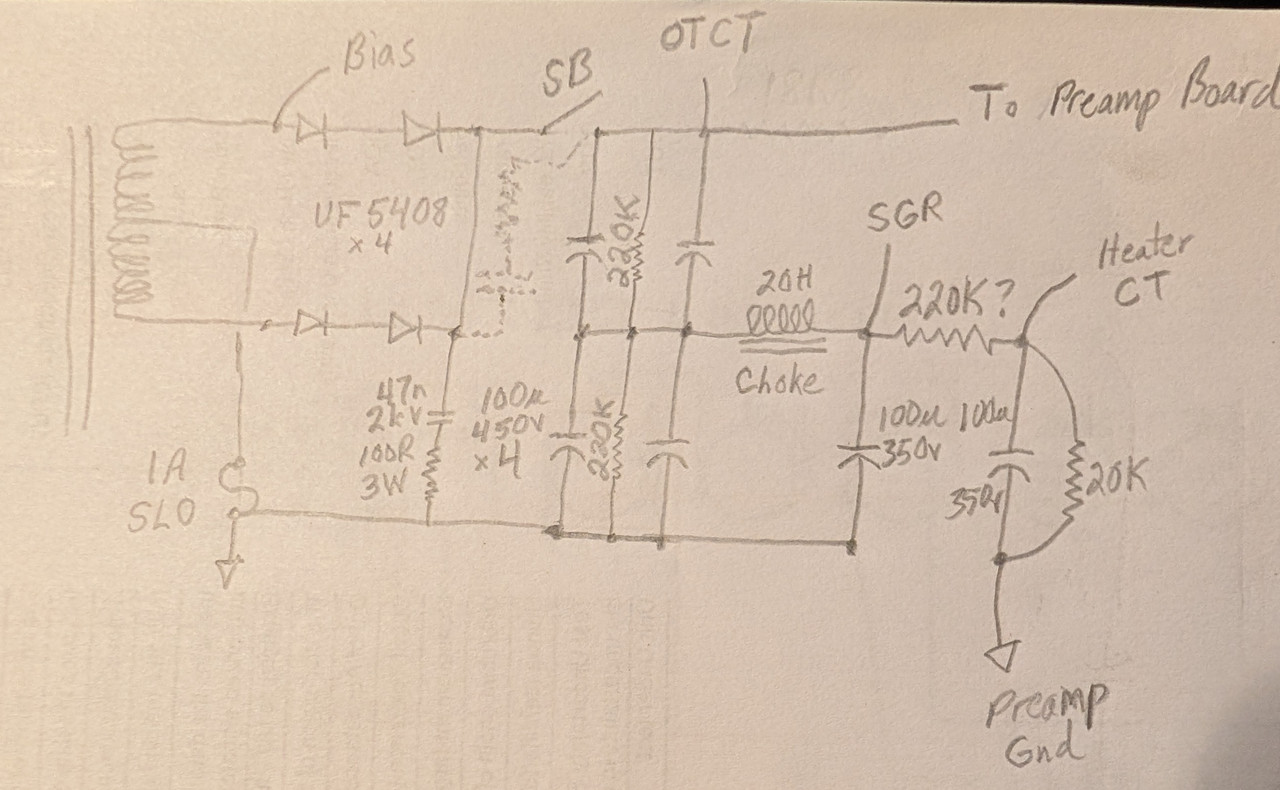
Here is what I originally drew but I added some dotted lines for what I think might be the right way. I have the resistor in but only because Gemini said so.
Early brewers were primarily women, mostly because it was deemed a woman's job. Mesopotamian men, of some 3,800 years ago, were obviously complete assclowns and had yet to realize the pleasure of brewing beer.
Sidestep the issue. Re-wire the SB switch to mute the signal at the PI.
Same external effects: no sound, instant re-start.
Internally, no current surges from the PT to rectifiers, to filter caps to opened filter caps when SB is switched to play.
Tube life is arguable, but fewer on/off cycles probably balances any change is life from more on-time.
And no snubbing on the switch is needed, as well as the switch not being under high voltage stress.
"For every complex problem there is an answer that is clear, simple, and wrong"
H. L. Mencken
Fischerman wrote: ↑Sun Jul 19, 2026 1:59 pm
Here is what I originally drew but I added some dotted lines for what I think might be the right way. I have the resistor in but only because Gemini said so.
With the dotted wiring the snubber is essentially in parallel with the reservoir cap(s) and will have no effect at all.
Edit: Please ignore post. I misread the schematic, sorry.
R.G. wrote: ↑Sun Jul 19, 2026 2:03 pm
Sidestep the issue. Re-wire the SB switch to mute the signal at the PI.
Same external effects: no sound, instant re-start.
Internally, no current surges from the PT to rectifiers, to filter caps to opened filter caps when SB is switched to play.
Tube life is arguable, but fewer on/off cycles probably balances any change is life from more on-time.
And no snubbing on the switch is needed, as well as the switch not being under high voltage stress.
So just move the switch to the 'To Preamp Board' side of the filters/OTCT connection. I like that, I don't mind the power tubes idling in SB nor the amp 'hard starting'. Just mainly want safe and quiet switching.
Thanks!
EDIT: now that I reread that you said switch 'the signal at the PI'. So from Treble to SB to PI? That's going to have to be shielded, right?
Or just ground the signal, boop just like that.
Early brewers were primarily women, mostly because it was deemed a woman's job. Mesopotamian men, of some 3,800 years ago, were obviously complete assclowns and had yet to realize the pleasure of brewing beer.
You can just ground the signal any convenient place to keep it out of the power amp. If you pick a place that is natively pulled to ground after a capacitor, that would be ideal. Just grounding the signal was what I had in mind, leaving the power supplies out of it entirely.
You will have to deal with the switch wires, as you picked out immediately. Shielded wire and so on may be needed. Another way might be to "cold switch" it to get really silent operation. An LED/MOSFET solid state relay like the Panasonic 769-AQY210EH, $1.83 at Mouser, would do it. 10ma into the LED makes the MOSFET side be a sub 100 ohm resistor.
"For every complex problem there is an answer that is clear, simple, and wrong"
H. L. Mencken
Stevem wrote: ↑Sun Jul 19, 2026 6:36 pm
Do what Danelectro did in the Silvertone 1484 for a standby, short out the two outputs of the PI together after the blocking caps.
That's a great idea too. This amp will have a dual-pot post-phase inverter MV. I was going to put it on the back.
Early brewers were primarily women, mostly because it was deemed a woman's job. Mesopotamian men, of some 3,800 years ago, were obviously complete assclowns and had yet to realize the pleasure of brewing beer.
Yeah, shorting the plates of the PI works well too. I tend to root for techniques that have at least one side grounded and not have signal in the wires, but the PI plates sure work.
Grounding the grid of the last preamp stage before the PI would be another place, although this might let more hiss through.
"For every complex problem there is an answer that is clear, simple, and wrong"
H. L. Mencken
Stevem wrote: ↑Sun Jul 19, 2026 6:36 pm
Do what Danelectro did in the Silvertone 1484 for a standby, short out the two outputs of the PI together after the blocking caps.
That's a great idea too. This amp will have a dual-pot post-phase inverter MV. I was going to put it on the back.