Princeton Reverb and Adjustable NFB placement/routing

Fender Amp Discussion

Moderators: pompeiisneaks, Colossal

User avatar
ViperDoc
Posts: 1247
Joined: Tue Dec 24, 2019 2:21 am
Location: Idaho

Princeton Reverb and Adjustable NFB placement/routing

Post by ViperDoc »

I'm jumping into a Princeton Reverb 12-inch combo project, and I'd like to add a 3-way adjustable NFB switch a la Rob Robinette. I just put one in a Tweed Deluxe and I love it. My question regards how he (Rob) puts the NFB switch all the way to the back left on the ground switch chassis hole. I wouldn't mind having it on the front, like a readily available voice switch on the front panel. If I ran the NFB wire to the front panel, "how close is close" to the vibrato jack and circuit before it causes issues? That seemed a problem to Mr. Robinette, and this is my first BFPR. I thought I could use shielded wire at least. Your thoughts are much appreciated.

Image

Image

Image
Just plug it in, man.
Stevem
Posts: 4989
Joined: Fri Jan 24, 2014 3:01 pm
Location: 1/3rd the way out one of the arms of the Milkyway.

Re: Princeton Reverb and Adjustable NFB placement/routing

Post by Stevem »

There is no reason it could not be placed on the front panel all the way over next to the pilot lamp, but that being said I need to ask why you are calling it a voicing switch as that statement leads me to think that you really do not know what effect negative feedback has on the amp and maybe even more so your playing?
When I die, I want to go like my Grandfather did, peacefully in his sleep.
Not screaming like the passengers in his car!

Cutting out a man's tongue does not mean he’s a liar, but it does show that you fear the truth he might speak about you!
User avatar
ViperDoc
Posts: 1247
Joined: Tue Dec 24, 2019 2:21 am
Location: Idaho

Re: Princeton Reverb and Adjustable NFB placement/routing

Post by ViperDoc »

Thanks, Steve! Maybe I used the wrong term. I was mainly referring to the location some of my other amps have these switches on them. My concern was where I could put a feedback switch without making the runs too long. The switch I put on my TD combo greatly improved headroom and lowered the gain somewhat. I really like the possibilities with it, and thought the front panel would be a good place for it.

Just out of curiosity, why would you put it by the lamp?
Just plug it in, man.
User avatar
M Fowler
Posts: 14034
Joined: Wed Jan 16, 2008 2:19 am
Location: Walcott ND

Re: Princeton Reverb and Adjustable NFB placement/routing

Post by M Fowler »

I've installed these 3 way switches on the back of Fender amps and the customers went nuts over the different gain structures this switch can produce.
Great for rocking out. Never put one on the front before but I'm sure it can be done with noise problems.

Mark
User avatar
ViperDoc
Posts: 1247
Joined: Tue Dec 24, 2019 2:21 am
Location: Idaho

Re: Princeton Reverb and Adjustable NFB placement/routing

Post by ViperDoc »

Maybe I should just put on the back. Easier that way.
Just plug it in, man.
Travis_HY
Posts: 63
Joined: Thu Aug 13, 2009 3:18 am

Re: Princeton Reverb and Adjustable NFB placement/routing

Post by Travis_HY »

ViperDoc wrote: Tue Sep 08, 2020 5:57 pm Maybe I should just put on the back. Easier that way.
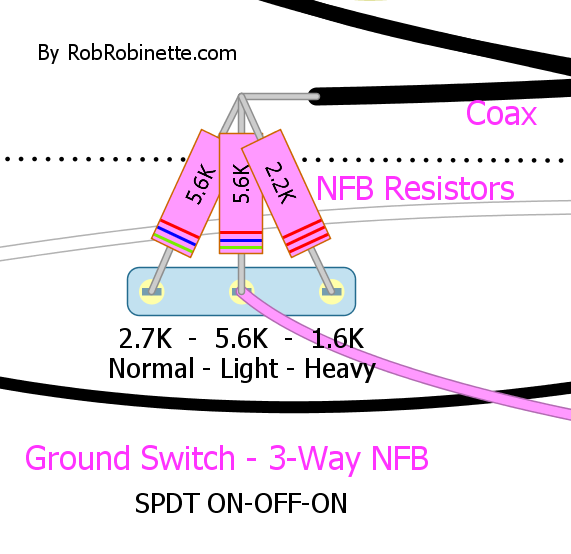
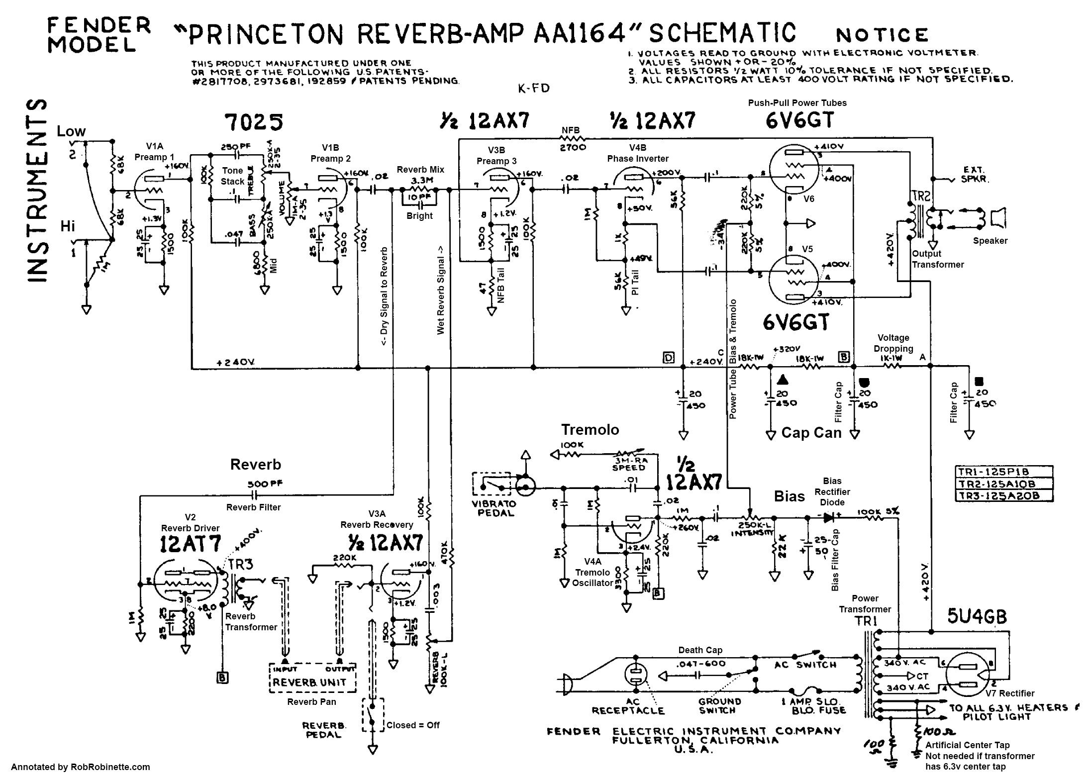
This is a cool mod on a lot of Fender amps, and on a Princeton Reverb my personal approach would be little different than the suggested three way switch. I’d personally like a variable resistor (a potentiometer) to vary the amount of feedback to my liking depending on what sound I am going for. This also gives the end user more options for those "in-between" settings, it costs about the same and it requires less parts overall than the 3-way switch. I’d use a 5k pot (the taper depends on the user’s tastes, but probably a linear B taper would work fine) keeping the aforementioned minimum of 1.5-1.6k feedback resistor when the pot is zero’d and about 6k when the Feedback control is turned all the way up. Meaning you would simply replace one of those resistors on the switch to a 1.5k resistor (The 2.2k in the second diagram would be fine if you want to keep the visual reference the same), then remove the other two resistors and route the wiper (middle lug) of the 5k pot to the speaker jack in the same fashion as the switch does in the diagrams. This would be my ideal configuration of this mod, but it may not be the ideal configuration for the end user if they don’t like tweaking things or they just want the three pre-set feedback settings.

Stability wise, you’ll probably be ok if you route the feedback wire along the back in the Ground Switch hole as per Rob Robinette’s suggestion because the amount of gain present isn’t too crazy. If having the pot all the way over in the Ground Switch is troublesome, you can replace the External Speaker jack with the pot (I’ve done this with assorted Fenders) and it would probably work fine as well. If it is really fickle, you could even try replacing the footswitch jack with a TRS jack so it doesn’t have discrete RCA jacks for the reverb and tremolo. Of course, you have to change the footswitch pedal cable end plug to a TRS as well, but I’d try the Ground Switch hole first and see what happens. There is really no way to tell if the wires or too long or if the placement of the pot is troublesome besides actually installing it in the amp in question and going forward (or not, hopefully!) from there.

Hope that helps!
"Genius manifests itself. You got a hammer. You either build a Cathedral or you build a shithouse." - Carl Schroeder
User avatar
ViperDoc
Posts: 1247
Joined: Tue Dec 24, 2019 2:21 am
Location: Idaho

Re: Princeton Reverb and Adjustable NFB placement/routing

Post by ViperDoc »

Cool idea. Thanks!
Just plug it in, man.
User avatar
ViperDoc
Posts: 1247
Joined: Tue Dec 24, 2019 2:21 am
Location: Idaho

Re: Princeton Reverb and Adjustable NFB placement/routing

Post by ViperDoc »

This is where it will live for now. I'm going to do the 3-way light-normal-heavy NFB mod and see how I like it.

Image
Just plug it in, man.
User avatar
ViperDoc
Posts: 1247
Joined: Tue Dec 24, 2019 2:21 am
Location: Idaho

Re: PRINCETON FIRE-UP W/ MASSIVE V1A CATHODE VOLTAGE

Post by ViperDoc »

So I "finished" wiring up my Princeton. It's a Mojo kit with a very few modifications, namely 3-way adjustable NFB, a buss wire on the board, a 0.001 uF cap off of V3B plate for a 12-inch speaker, a 470R PI grid stop resistor, 1.5K grid leak resistors and 470R screen resistors on the power tubes, and a ground switch delete. OK, maybe more than a few, but I thought I'd give Rob Robinette's upgrades a nod on this build.

I powered up the chassis and found the following:
1) bulb limiter test passed.
2) Full 121VAC power-up shows 6.3 VAC across all heaters, 350VAC on the PT secondary without tubes
3) Power-up with rectifier tube shows no red-plating.
4) Power-up with preamp tubes shows errant voltages.
5) Power-up with Preamp and power tubes shows 35 VAC on the V1A cathode pin. V1A plate is supposed to be 150 VDC, but it's just over 300. I stopped reading voltages and turned the amp off.

Obviously I've wired something wrong, at least. Here are some gut shots:

Image
Image
Image
Image
Image
Image
Image
Image

The original layout is posted above.
Last edited by ViperDoc on Sat Sep 19, 2020 6:15 am, edited 1 time in total.
Just plug it in, man.
User avatar
ViperDoc
Posts: 1247
Joined: Tue Dec 24, 2019 2:21 am
Location: Idaho

Re: Princeton Reverb and Adjustable NFB placement/routing

Post by ViperDoc »

I think I just found my problem...

Regardless of how much effort one takes to install a grounding scheme, unless it's actually *grounded*, well...

Image

I wired up my inputs last and forgot to ground the buss wire to the jack. I wired the buss up to the jack and problem solved! The amp sounds pretty good!

I still have to wire up and install my reverb tank.

I notice the tremolo sound is a) incredibly fast, and b) barely noticeable even when the intensity is cranked. I don't mind a mellow tremolo sound, but this particular version out of my hands doesn't sound all that useable.
Last edited by ViperDoc on Sat Sep 19, 2020 6:21 am, edited 2 times in total.
Just plug it in, man.
User avatar
Deric
Posts: 775
Joined: Sun Jan 14, 2007 2:56 am

Re: Princeton Reverb and Adjustable NFB placement/routing

Post by Deric »

To slow down the tremolo replace one of the .01 caps in the oscillator with a .02 (so you have .01, .02, .02 instead of .01, .01, .02). For more a more intense trem replace the cathode cap/resistor of the oscillator (3.3K/25u) with a red LED.
Deric®
User avatar
ViperDoc
Posts: 1247
Joined: Tue Dec 24, 2019 2:21 am
Location: Idaho

Re: Princeton Reverb and Adjustable NFB placement/routing

Post by ViperDoc »

Thanks, Deric.
Just plug it in, man.
User avatar
ViperDoc
Posts: 1247
Joined: Tue Dec 24, 2019 2:21 am
Location: Idaho

Re: Princeton Reverb and Adjustable NFB placement/routing

Post by ViperDoc »

I just bench tested the two reverb tanks I picked up: the stock 4AB3C1B long, 2-spring tank and an alternative 8AB2A1B short 3-spring tank. All I can say is WOW. Tube reverb, who knew! The short, 3-spring tank is going in the combo, no doubt. The long tank becomes aquatic after about 2.5 on the knob, and while the short 3-spring can get there, it sounds much more musical even in the higher ranges. What a great sounding reverb. I've been testing it through a Warehouse ET-65 1x12 extension cab and it sounds really good.

Image

I can also say this amp is utterly and completely silent except for a bit of noise when dimed. I've marked the foil end on the orange drops on my last three builds and they're all silent. I learned that from some of you here, so thank you for the hot tip. It works.
Just plug it in, man.
User avatar
ViperDoc
Posts: 1247
Joined: Tue Dec 24, 2019 2:21 am
Location: Idaho

Re: Princeton Reverb and Adjustable NFB placement/routing

Post by ViperDoc »

Looking the Princeton over, if I wanted to delete the tremolo part of the circuit altogether, is it as simple as deleting the intensity pot and everything to the left of it on the schematic?

Image
Just plug it in, man.
User avatar
ViperDoc
Posts: 1247
Joined: Tue Dec 24, 2019 2:21 am
Location: Idaho

Re: Princeton Reverb and Adjustable NFB placement/routing

Post by ViperDoc »

Deric wrote: Fri Sep 18, 2020 11:02 pm To slow down the tremolo replace one of the .01 caps in the oscillator with a .02 (so you have .01, .02, .02 instead of .01, .01, .02). For more a more intense trem replace the cathode cap/resistor of the oscillator (3.3K/25u) with a red LED.
Just to clarify here...

I've seen posts here about replacing the neon bulb in a classic blackface roach tremolo design with a "roach upgrade" LED that is shrink-wrapped facing a photo-resistor.

With your suggestion, does the LED alone intensify the effect? Like this?

Image
Just plug it in, man.
Post Reply