Please clarify.
Calculating required transformer voltage specs for 100w marshall
Moderators: pompeiisneaks, Colossal
-
flemingmras
- Posts: 111
- Joined: Sat May 02, 2026 5:07 am
1 others liked this
Re: Calculating required transformer voltage specs for 100w marshall
I'm pretty sure the Heyboer transformers used in Metro's first gen 69 Super Lead Plexi kits (HTS-6010) was a replica of the Dagnall T2562 based on the specs (1.875" stack, 180-0-180 @ 115V). This transformer was available as both a standup (T3715?) and a laydown type. This would be the type offered until he released the Drake 1203-80 and Dagnall C1998 clones in 2006.Roe wrote: ↑Tue May 12, 2026 4:08 pmThe Drake 1203-80 had a 2.5" stack, whereas the Dagnall t2562 only had 1.8". The latter sagged more than the latter and got warmer, even though the steel quality could be better.martin manning wrote: ↑Tue May 12, 2026 3:52 pmInteresting. I recall the problems that George M had with his "better" PT's some years ago. Given that the core dimensions are similar, wouldn't it be hard to fit larger wire into the same window? Perhaps better steel might have something to do with it?
The metro PT was based on the former, but increased the current capability somewhat, perhaps due to better steel and thicker wire
Re: Calculating required transformer voltage specs for 100w marshall
The Dagnall t2562 introduced in 1967-68, has thinner laminations and gets warmer than the Drake 1203-80 typically. The Dagnall normally sags around 20% at full power (e.g., from 500v at idle to ca 400v at full power). The Drake tends to sag a little less. However, in 1967 plate voltages went from ca 500v at idle to 460v (for the latter, see here https://www.drtube.com/schematics/marshall/100w-67.gif)
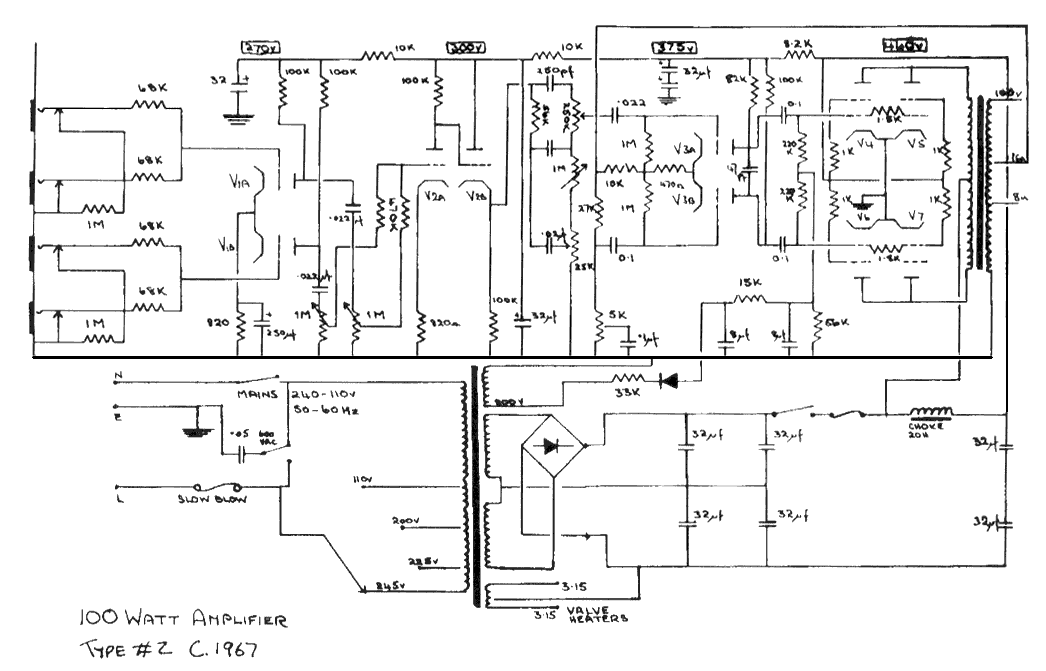
Last edited by Roe on Wed May 13, 2026 7:37 am, edited 1 time in total.
Re: Calculating required transformer voltage specs for 100w marshall
The later PTs were certainly based on the Drake 1203-80 but rated for 450ma. George said the early PTs had higher voltage (500v at idle, not 480v as earlier amp) but he did not mention changing the stack/laminations or construction from Dagnall to Drake specs.flemingmras wrote: ↑Tue May 12, 2026 7:15 pmI'm pretty sure the Heyboer transformers used in Metro's first gen 69 Super Lead Plexi kits (HTS-6010) was a replica of the Dagnall T2562 based on the specs (1.875" stack, 180-0-180 @ 115V). This transformer was available as both a standup (T3715?) and a laydown type. This would be the type offered until he released the Drake 1203-80 and Dagnall C1998 clones in 2006.Roe wrote: ↑Tue May 12, 2026 4:08 pmThe Drake 1203-80 had a 2.5" stack, whereas the Dagnall t2562 only had 1.8". The latter sagged more than the latter and got warmer, even though the steel quality could be better.martin manning wrote: ↑Tue May 12, 2026 3:52 pmInteresting. I recall the problems that George M had with his "better" PT's some years ago. Given that the core dimensions are similar, wouldn't it be hard to fit larger wire into the same window? Perhaps better steel might have something to do with it?
The metro PT was based on the former, but increased the current capability somewhat, perhaps due to better steel and thicker wire
Interestingly, Marshall themselves changed from a Dagnall t2562 style PT w. 1.8" stack to a fatter 2.5 stack like the 1203 on recent RIs. The transformers are made by Dagnall but seem to follow the 1203 rather than the t2562
Re: Calculating required transformer voltage specs for 100w marshall
On the 1203-80, the HT secondary has 0.40mm wire. heater has 2.4mm, bias winding has 0.25mm.flemingmras wrote: ↑Tue May 12, 2026 4:59 pmYou assume they used enough wire to completely fill up that window in an original.martin manning wrote: ↑Tue May 12, 2026 3:52 pmInteresting. I recall the problems that George M had with his "better" PT's some years ago. Given that the core dimensions are similar, wouldn't it be hard to fit larger wire into the same window? Perhaps better steel might have something to do with it?
The HTS-6010 uses #25 magnet wire in the secondary. I believe the 1203-80 clones did as well. This wire has a resistance spec of 32.37 ohms per 1K feet at 20°C.
Unfortunately, Heyboer doesn't provide any sort of load testing data. I have two of these transformers on order and plan to do some load testing on them.
#25 magnet wire seems to be 0.454mm, whereas #26 is 0.404mm.
#25 handles 457ma [metro/heyboer]
#26 handles 361ma [Drake/Marstran]
#27 handles 288ma [Dagnall?]
See https://metersuk.co.uk/wp-content/uploa ... RT-1-w.jpg

-
flemingmras
- Posts: 111
- Joined: Sat May 02, 2026 5:07 am
Re: Calculating required transformer voltage specs for 100w marshall
Where did you find the wire sizes used on the originals?Roe wrote: ↑Wed May 13, 2026 8:16 amOn the 1203-80, the HT secondary has 0.40mm wire. heater has 2.4mm, bias winding has 0.25mm.
#25 magnet wire seems to be 0.454mm, whereas #26 is 0.404mm.
#25 handles 457ma [metro/heyboer]
#26 handles 361ma [Drake/Marstran]
#27 handles 288ma [Dagnall?]
See https://metersuk.co.uk/wp-content/uploa ... RT-1-w.jpg
Re: Calculating required transformer voltage specs for 100w marshall
the 1203-80 was measured when it was rewound. the Metro was measured by you in the post above. The Dagnall is a mere suspicion (based on current ratings of recreations), therefore the question mark.flemingmras wrote: ↑Wed May 13, 2026 12:09 pmWhere did you find the wire sizes used on the originals?Roe wrote: ↑Wed May 13, 2026 8:16 amOn the 1203-80, the HT secondary has 0.40mm wire. heater has 2.4mm, bias winding has 0.25mm.
#25 magnet wire seems to be 0.454mm, whereas #26 is 0.404mm.
#25 handles 457ma [metro/heyboer]
#26 handles 361ma [Drake/Marstran]
#27 handles 288ma [Dagnall?]
See https://metersuk.co.uk/wp-content/uploa ... RT-1-w.jpg
-
flemingmras
- Posts: 111
- Joined: Sat May 02, 2026 5:07 am
1 others liked this
Re: Calculating required transformer voltage specs for 100w marshall
And here is where things get even more interesting...
The stack on the Metro 1203-80 measures out to 2", whereas an original 1203-80 has a 2.5" stack. They also didn't use the right size magnet wire. For Metro to even associate them with the 1203-80 part number was a bit of a stretch. I'm also not sure why they decided on that one to be "the standard" when Marshall only used those for maybe a year.
The stack on the Metro 1203-80 measures out to 2", whereas an original 1203-80 has a 2.5" stack. They also didn't use the right size magnet wire. For Metro to even associate them with the 1203-80 part number was a bit of a stretch. I'm also not sure why they decided on that one to be "the standard" when Marshall only used those for maybe a year.
-
martin manning

- Posts: 14936
- Joined: Sun Jul 06, 2008 12:43 am
- Location: 39°06' N 84°30' W
1 others liked this
-
martin manning
- Posts: 14936
- Joined: Sun Jul 06, 2008 12:43 am
- Location: 39°06' N 84°30' W
1 others liked this
Re: Calculating required transformer voltage specs for 100w marshall
I don't think a one AWG step would add much voltage sag. That will only change the resistance per foot by ~20%, which won't result in anything like the 100 or so volts that has been reported. My money is on the core size, or perhaps the steel.
-
flemingmras
- Posts: 111
- Joined: Sat May 02, 2026 5:07 am
Re: Calculating required transformer voltage specs for 100w marshall
Eh don't kid yourself. One size is about an 8-10 ohm per 1K feet difference. Number of turns and inductance I'm sure also plays a part here.martin manning wrote: ↑Wed May 13, 2026 4:21 pm I don't think a one AWG step would add much voltage sag. That will only change the resistance per foot by ~20%, which won't result in anything like the 100 or so volts that has been reported. My money is on the core size, or perhaps the steel.
Re: Calculating required transformer voltage specs for 100w marshall
PT sag only depends on secondary and reflected primary DCR - not on core size or material.martin manning wrote: ↑Wed May 13, 2026 4:21 pm I don't think a one AWG step would add much voltage sag.
Total B+ sag also depends on reservoir cap value.
Re: Calculating required transformer voltage specs for 100w marshall
Thanks a lot!Roe wrote: ↑Wed May 13, 2026 7:32 am The Dagnall t2562 introduced in 1967-68, has thinner laminations and gets warmer than the Drake 1203-80 typically. The Dagnall normally sags around 20% at full power (e.g., from 500v at idle to ca 400v at full power). The Drake tends to sag a little less. However, in 1967 plate voltages went from ca 500v at idle to 460v (for the latter, see here https://www.drtube.com/schematics/marshall/100w-67.gif)
Re: Calculating required transformer voltage specs for 100w marshall
yes, 32uf on the mains supply of early 100w amps contributes to sag. even 50uf sags a bitHelmholtz wrote: ↑Wed May 13, 2026 4:55 pmPT sag only depends on secondary and reflected primary DCR - not on core size or material.martin manning wrote: ↑Wed May 13, 2026 4:21 pm I don't think a one AWG step would add much voltage sag.
Total B+ sag also depends on reservoir cap value.
-
martin manning
- Posts: 14936
- Joined: Sun Jul 06, 2008 12:43 am
- Location: 39°06' N 84°30' W
1 others liked this
Re: Calculating required transformer voltage specs for 100w marshall
I was thinking if the core ever got close to saturating the energy transfer would suffer, but that would result in severe overheating I guess. Hammond's 100W Marshall PT shows 21 ohms DCR, so an increase of 20% is only 4 ohms. I have run some interesting transient simulations to try and get an idea of how the power amp responds to a full power burst, and how much sag to expect. !00 volts seems excessive.Helmholtz wrote: ↑Wed May 13, 2026 4:55 pmPT sag only depends on secondary and reflected primary DCR - not on core size or material.martin manning wrote: ↑Wed May 13, 2026 4:21 pm I don't think a one AWG step would add much voltage sag.
Total B+ sag also depends on reservoir cap value.