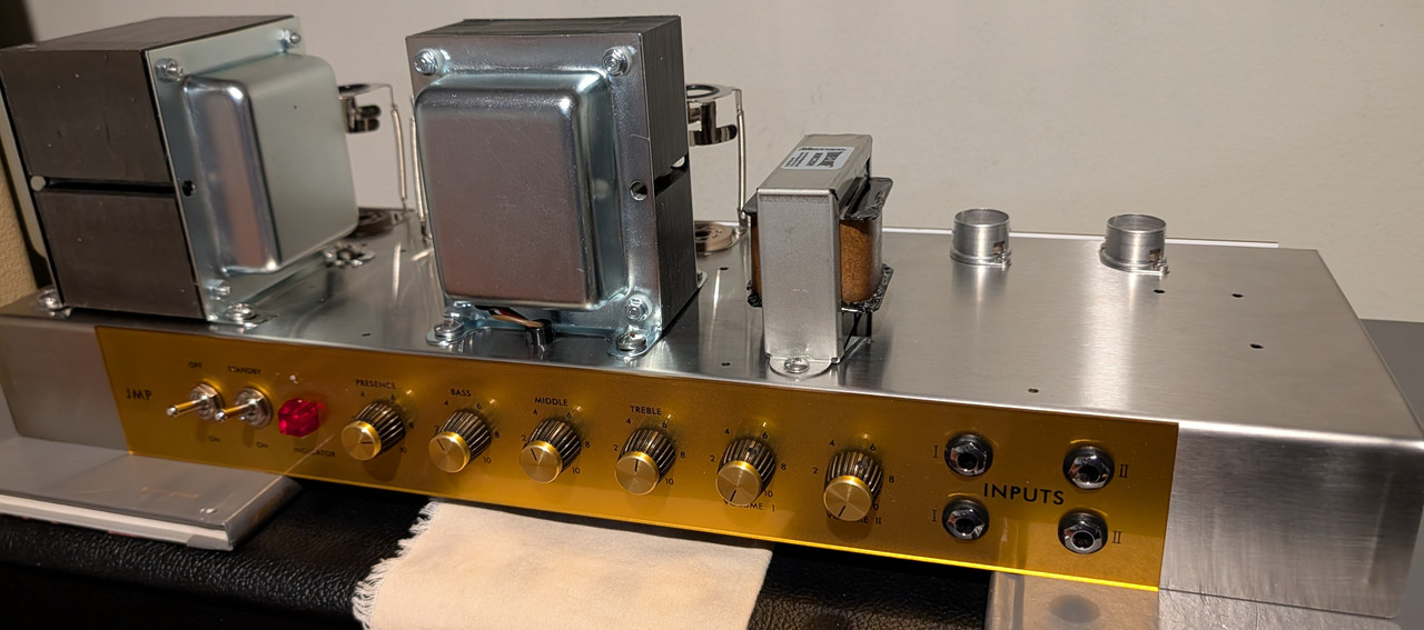
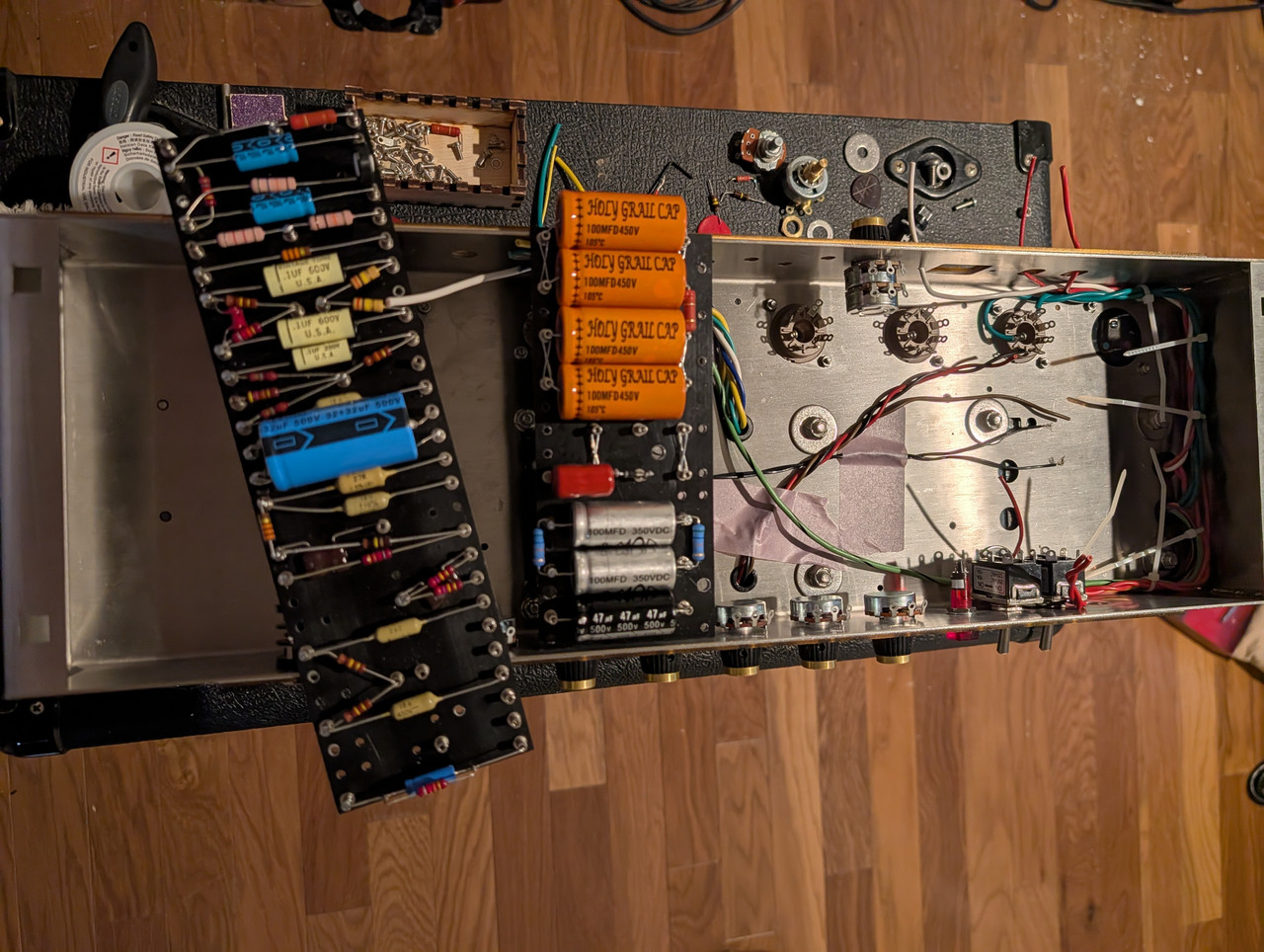
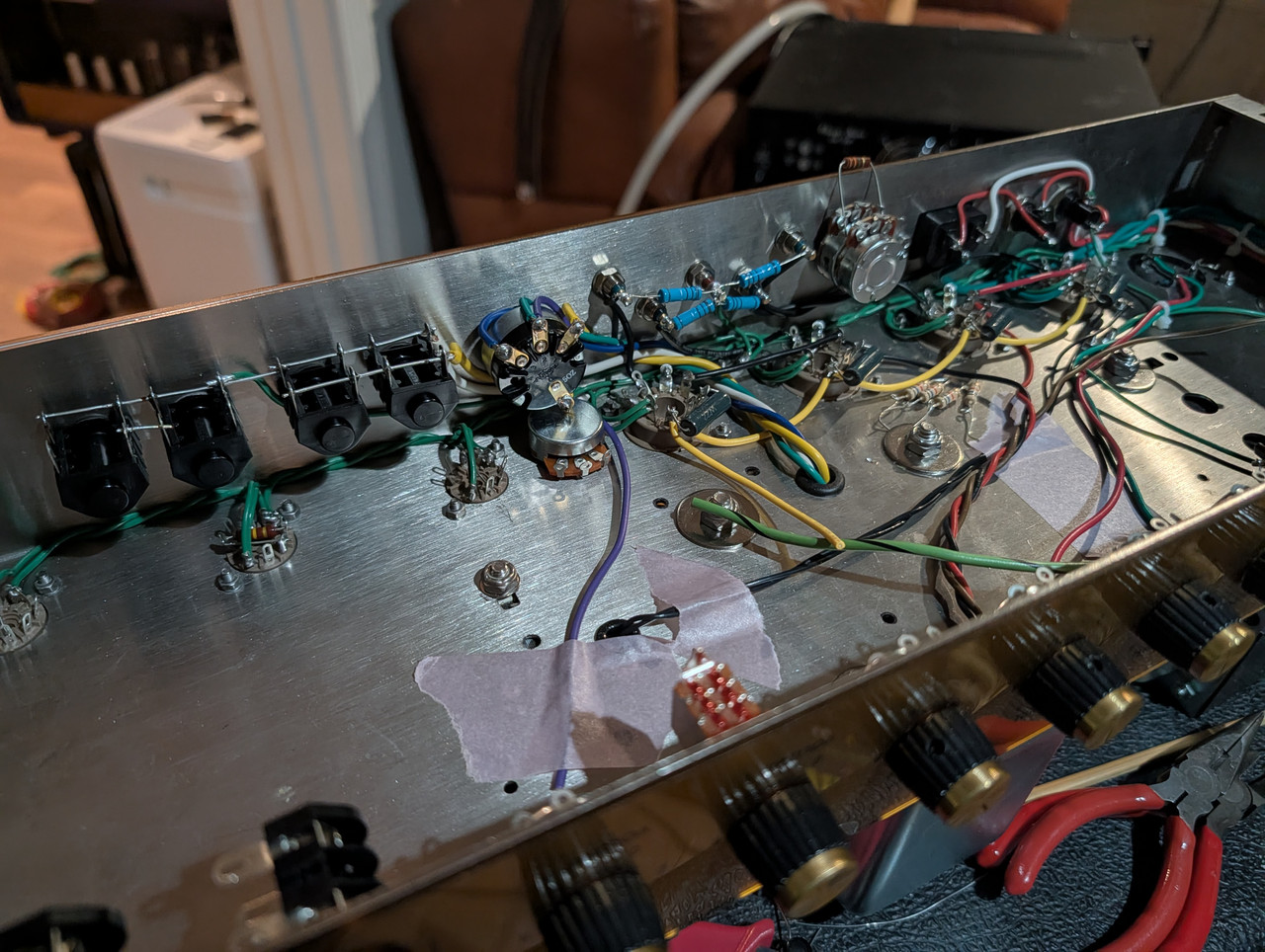
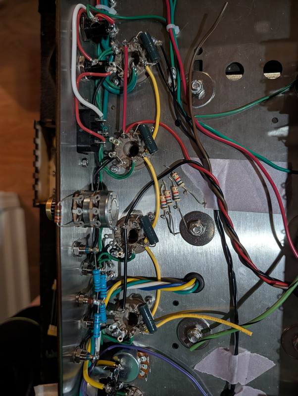
I did a Gilmour Hiwatt and an EVH Superlead so I decided to do a Jimi JTM100. They run really high voltages which just invites problems so with the help of this community I think I've got the right way to go. I finally got around to swapping the endbells on the PT (just so they look the same as the OT ) and then modifying chassis for new mounting holes. This chassis wasn't punched for a 3" stack.
It started with a Ceriatone West Coast JH Mod kit so everything fits nice and easy...except the transformers. Lots of parts swaps just because.
It's a start!
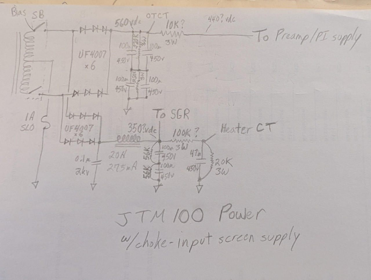
Here's the schematic of the power supply with the choke-input screen supply. The B+ should be 560v but the other voltages are just targets/guesses.
Early brewers were primarily women, mostly because it was deemed a woman's job. Mesopotamian men, of some 3,800 years ago, were obviously complete assclowns and had yet to realize the pleasure of brewing beer.
SamRE wrote: ↑Mon Aug 31, 2026 12:07 am
Every chance I'm asking a stupid question, but how did you get those numbers for the DC voltages?
The 560v B+ is from the mfr of the PT (Mercury). The others are simply guesses/targets. From previous threads about the choke-input screen supply I should expect 60%-65% of B+ there. I'm probably being optimistic by targeting 350v there. The preamp and bias voltage are easily adjusted by resistor swaps.
Early brewers were primarily women, mostly because it was deemed a woman's job. Mesopotamian men, of some 3,800 years ago, were obviously complete assclowns and had yet to realize the pleasure of brewing beer.
SamRE wrote: ↑Mon Aug 31, 2026 12:07 am
Every chance I'm asking a stupid question, but how did you get those numbers for the DC voltages?
The 560v B+ is from the mfr of the PT (Mercury). The others are simply guesses/targets. From previous threads about the choke-input screen supply I should expect 60%-65% of B+ there. I'm probably being optimistic by targeting 350v there. The preamp and bias voltage are easily adjusted by resistor swaps.
If it's the MP100-67S, that runs at 208V per side w/ a CT. With a full-wave/2-Phase rectifier like in your sketch, you'd be getting 280-290V for the main B+ rail wouldn't you?
Unless i'm missing something, I think you'd need a bridge rectifier to get the full 560V B+, in which case you could run the CT to the junction between the series connected filter caps and run the choke for the screens off of that like in the Hendrix WCM Ceriatone kit.
I totally understand if I've gotten this wrong, but I thought I'd mention it.
SamRE wrote: ↑Mon Aug 31, 2026 12:07 am
Every chance I'm asking a stupid question, but how did you get those numbers for the DC voltages?
The 560v B+ is from the mfr of the PT (Mercury). The others are simply guesses/targets. From previous threads about the choke-input screen supply I should expect 60%-65% of B+ there. I'm probably being optimistic by targeting 350v there. The preamp and bias voltage are easily adjusted by resistor swaps.
If it's the MP100-67S, that runs at 208V per side w/ a CT. With a full-wave/2-Phase rectifier like in your sketch, you'd be getting 280-290V for the main B+ rail wouldn't you?
Unless i'm missing something, I think you'd need a bridge rectifier to get the full 560V B+, in which case you could run the CT to the junction between the series connected filter caps and run the choke for the screens off of that like in the Hendrix WCM Ceriatone kit.
I totally understand if I've gotten this wrong, but I thought I'd mention it.
This is the M3-66P but stand-up with leads. It has just two secondaries; 417-0-417 and 6.3v @ 10A. I specifically asked my contact at Mercury about this (with schematics) and he assured me, FWCT not FW bridge. This was the way Marshall did it in 1966 before they switched to the method you are describing.
But thanks for that, I like having extra sets of eyes on my projects. I know just enough to get into trouble!
Early brewers were primarily women, mostly because it was deemed a woman's job. Mesopotamian men, of some 3,800 years ago, were obviously complete assclowns and had yet to realize the pleasure of brewing beer.
Fischerman wrote: ↑Mon Aug 31, 2026 2:03 am
The 560v B+ is from the mfr of the PT (Mercury). The others are simply guesses/targets. From previous threads about the choke-input screen supply I should expect 60%-65% of B+ there. I'm probably being optimistic by targeting 350v there. The preamp and bias voltage are easily adjusted by resistor swaps.
If it's the MP100-67S, that runs at 208V per side w/ a CT. With a full-wave/2-Phase rectifier like in your sketch, you'd be getting 280-290V for the main B+ rail wouldn't you?
Unless i'm missing something, I think you'd need a bridge rectifier to get the full 560V B+, in which case you could run the CT to the junction between the series connected filter caps and run the choke for the screens off of that like in the Hendrix WCM Ceriatone kit.
I totally understand if I've gotten this wrong, but I thought I'd mention it.
This is the M3-66P but stand-up with leads. It has just two secondaries; 417-0-417 and 6.3v @ 10A. I specifically asked my contact at Mercury about this (with schematics) and he assured me, FWCT not FW bridge. This was the way Marshall did it in 1966 before they switched to the method you are describing.
But thanks for that, I like having extra sets of eyes on my projects. I know just enough to get into trouble!
Ah, understood. Fair old Iron that is, happy to lend an extra pair of eyes.
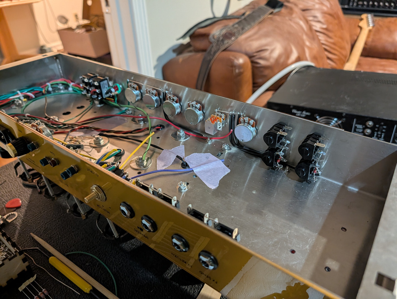
Floor wiring done. Not really a fan of the 6v pilot that requires an extra resistor but whatever. I need to take a break from it. Hopefully finish it next weekend.
I really don't like having a plain old Alpha pot sticking up outside of the amp as a bias adjustment. Worse is where they put it inside the amp! I had never intended to put the bias pot there but an adjustable NFB would have been nice. I decided to leave it so I can easily dial in the NFB during testing but it's probably coming out after that. I could rotate the impedance selector but the shaft has a flat for the knob setscrew so that kind of dictates it's orientation. There's only a few mm clearance.
Extra 3M3 on MV to balance the two pots (238k and 220k).
Early brewers were primarily women, mostly because it was deemed a woman's job. Mesopotamian men, of some 3,800 years ago, were obviously complete assclowns and had yet to realize the pleasure of brewing beer.
Extra 3M3 on MV to balance the two pots (238k and 220k).
That won't improve the balance.
Imbalance is caused by difference in taper, not end-to-end resistance.
Are you saying I should just leave it at 238k/220k? FWIW, these pots will be in parallel with 200k resistors on the board.
I've done a lot of these MVs and I've found the best sound is to just put the dual 250k pot in parallel with the existing 220k on the board. I originally used the version in Weber's book but Dave Friedman found this tweeked method sounds/responds better and I agree.
Early brewers were primarily women, mostly because it was deemed a woman's job. Mesopotamian men, of some 3,800 years ago, were obviously complete assclowns and had yet to realize the pleasure of brewing beer.
Fischerman wrote: ↑Wed Sep 09, 2026 5:43 pm
Are you saying I should just leave it at 238k/220k? FWIW, these pots will be in parallel with 200k resistors on the board.
Parallel resistors will change the PI load but won't change taper and balance.
Fischerman wrote: ↑Wed Sep 09, 2026 5:43 pm
Are you saying I should just leave it at 238k/220k? FWIW, these pots will be in parallel with 200k resistors on the board.
Parallel resistors will change the PI load but won't change taper and balance.
When you say 'balance', are you referring to PI output balance? That wasn't really what I meant when I originally wrote 'balance' above. I will admit that I was assuming a similar taper. So it seemed having the same starting points (220k) and ending points (~0) and 'very similar' taper would at least improve things. But your original statement was 'no improvement' and I'm just trying to understand.
Also I was thinking, when cranked and there is grid current; having a similar resistance for each side would be better than not.
Early brewers were primarily women, mostly because it was deemed a woman's job. Mesopotamian men, of some 3,800 years ago, were obviously complete assclowns and had yet to realize the pleasure of brewing beer.
I'm referring to the balance of the two MV output signals (which are the power tube power grid signals).
A pot is a (variable) voltage divider. It's output at the wiper is a certain percentage (depending on pot setting and taper) of the input voltage. Output doesn't depend on total pot resistance.
Helmholtz wrote: ↑Wed Sep 09, 2026 5:03 pm
I measured a few dual pots and found ganging differences of 20% to over 30%.
Even expensive Alps stereo pots were worse than 10%.
 ) and then modifying chassis for new mounting holes. This chassis wasn't punched for a 3" stack.