It has been a year since i really touched an amp. I am very rusty, and was not an expert to begin with. That Said.....
...when the screens draw current, it comes "up" through the cathode with the Plate Current, right.?
In the Bassman schem below.....is the cap after the choke the source for the screen electrons, or does the reservoir cap(s) also supply current to the screens.?
Thank You
http://el34world.com/charts/Schematics/ ... ematic.pdf
screen current
Moderators: pompeiisneaks, Colossal
screen current
-------------------------------------
https://www.youtube.com/watch?v=zhvDOxvfvhw
https://www.youtube.com/watch?v=KWXulD-gxuw @ 1:40
https://www.youtube.com/watch?v=iTxaQu4NfI8
https://www.youtube.com/watch?v=_BSCS_hl0iA
https://www.youtube.com/watch?v=zhvDOxvfvhw
https://www.youtube.com/watch?v=KWXulD-gxuw @ 1:40
https://www.youtube.com/watch?v=iTxaQu4NfI8
https://www.youtube.com/watch?v=_BSCS_hl0iA
Re: screen current
Electrons flow from the cathode, conventional 'current' 'flows' from positive to negative - i.e. in the opposite direction to electrons.C Moore wrote: ...when the screens draw current, it comes "up" through the cathode with the Plate Current, right.?...
Having noted that - yes. Tube current (measured at the cathode) is the sum of plate current and screen current (in a tetrode or pentode).
As conventional current 'flows' from positive to negative, then the screen node filter cap is the point at which screen current (and pre-amp tube current) 'flows' through.C Moore wrote: In the Bassman schem below.....is the cap after the choke the source for the screen electrons, or does the reservoir cap(s) also supply current to the screens.?
Thank You
http://el34world.com/charts/Schematics/ ... ematic.pdf
The reservoir cap is earlier in the power supply chain that the screen node filter cap, therefore screen current, and preamp current 'flows' in the reservoir cap - along with the output tube plate current.
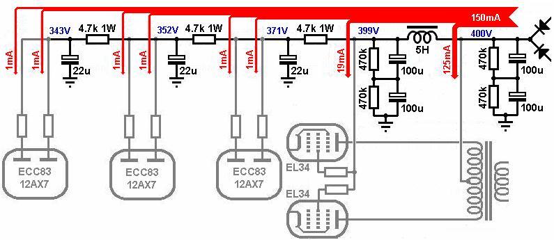
This diagram from Merlin Blencowe's website:
[img:795:345]http://www.valvewizard.co.uk/smoothing6.jpg[/img]
Re: screen current
Is it possible to stick with electron flow.? 
My question is.....if screen current is being drawn from the cap after the choke...through the cathode...through screens...back to pos of cap...and back to tranny.......how do the electrons keep track of where they came from and are going to.?
If Plate and Screen current are both coming from the cathode, what is to keep the screens (or vice versa) just pulling their current from the reservoir caps.?
Thank You
Last edited by C Moore on Tue Nov 15, 2016 2:01 pm, edited 1 time in total.
-------------------------------------
https://www.youtube.com/watch?v=zhvDOxvfvhw
https://www.youtube.com/watch?v=KWXulD-gxuw @ 1:40
https://www.youtube.com/watch?v=iTxaQu4NfI8
https://www.youtube.com/watch?v=_BSCS_hl0iA
https://www.youtube.com/watch?v=zhvDOxvfvhw
https://www.youtube.com/watch?v=KWXulD-gxuw @ 1:40
https://www.youtube.com/watch?v=iTxaQu4NfI8
https://www.youtube.com/watch?v=_BSCS_hl0iA
Re: screen current
There are several ways to visualize the process, potential flow, current flow, electron flow, and hole flow in semiconductors. The easiest way to see it , perhaps is :
Electons boil off the cathode and are attracted to the high voltage at either the screen or plate, depending on where they physically travel. If electrons in the stream hit a screen wire, they travel to the voltage source at the top of that cap. Most of the electrons in the stream miss the screen grid wire and hit the plate, those elecrons travel through the output transformer to the voltage source at the top of the "reservoir" cap.
Electons boil off the cathode and are attracted to the high voltage at either the screen or plate, depending on where they physically travel. If electrons in the stream hit a screen wire, they travel to the voltage source at the top of that cap. Most of the electrons in the stream miss the screen grid wire and hit the plate, those elecrons travel through the output transformer to the voltage source at the top of the "reservoir" cap.
Tube junkie that aspires to become a tri-state bidirectional buss driver.
Re: screen current
Yeah...that makes sense...Thank You.
So how important is that screen cap as far as DC Ripple is concerned. Is most of the ripple gone after the reservoir, and the following caps are mostly providing Decoupling...if that is the correct term.?
Or do the Screen and Pre Amp caps provide a lot of ripple relief also.?
Thanks
So how important is that screen cap as far as DC Ripple is concerned. Is most of the ripple gone after the reservoir, and the following caps are mostly providing Decoupling...if that is the correct term.?
Or do the Screen and Pre Amp caps provide a lot of ripple relief also.?
Thanks
-------------------------------------
https://www.youtube.com/watch?v=zhvDOxvfvhw
https://www.youtube.com/watch?v=KWXulD-gxuw @ 1:40
https://www.youtube.com/watch?v=iTxaQu4NfI8
https://www.youtube.com/watch?v=_BSCS_hl0iA
https://www.youtube.com/watch?v=zhvDOxvfvhw
https://www.youtube.com/watch?v=KWXulD-gxuw @ 1:40
https://www.youtube.com/watch?v=iTxaQu4NfI8
https://www.youtube.com/watch?v=_BSCS_hl0iA
Re: screen current
The more current drawn, the more ripple will stand out, as the pulses of DC try to fill the caps. Statically, the supply looks very clean, under heavy load, not so much. So the combination of the caps and the values of the resistors in the string, while providing isolation between stages, also provide better filtering by changing the ratio of ripple to clean DC voltage. The effect of ripple at the screen is greater than at the plate as the screen directly controls the flow through the tube.
Tube junkie that aspires to become a tri-state bidirectional buss driver.
Re: screen current
OK, Yeah.....good point about the screens. 
I Appreciative It...Thanks Again
I Appreciative It...Thanks Again
-------------------------------------
https://www.youtube.com/watch?v=zhvDOxvfvhw
https://www.youtube.com/watch?v=KWXulD-gxuw @ 1:40
https://www.youtube.com/watch?v=iTxaQu4NfI8
https://www.youtube.com/watch?v=_BSCS_hl0iA
https://www.youtube.com/watch?v=zhvDOxvfvhw
https://www.youtube.com/watch?v=KWXulD-gxuw @ 1:40
https://www.youtube.com/watch?v=iTxaQu4NfI8
https://www.youtube.com/watch?v=_BSCS_hl0iA
-
martin manning

- Posts: 13549
- Joined: Sun Jul 06, 2008 12:43 am
- Location: 39°06' N 84°30' W
Re: screen current
But in pp it's common mode, and so it will be cancelled in the OT.TUBEDUDE wrote:The effect of ripple at the screen is greater than at the plate as the screen directly controls the flow through the tube.
Re: screen current
In a CLC filter, the screen node filter cap is there mainly to provide decoupling to stabilise the 'DC-end' of the choke (without which, the choke's self-inductance wouldn't be as effective).
He who dies with the most tubes... wins
Re: screen current
I think that with p-p, the g2 ripple still needs needs keeping under tight control, as, in addition to the ripple signal itself, sum and difference harmonics of its mixing with the g1 signal will be createdmartin manning wrote:But in pp it's common mode, and so it will be cancelled in the OT.TUBEDUDE wrote:The effect of ripple at the screen is greater than at the plate as the screen directly controls the flow through the tube.
Imperfections in system balance will tend to allow a degree of common mode nasties through, and signal asymmetry may cause sum and difference artefacts that aren't common mode?
My band:- http://www.youtube.com/user/RedwingBand
Re: screen current
Thanks Again...btw.TUBEDUDE wrote:The more current drawn, the more ripple will stand out, as the pulses of DC try to fill the caps. Statically, the supply looks very clean, under heavy load, not so much. So the combination of the caps and the values of the resistors in the string, while providing isolation between stages, also provide better filtering by changing the ratio of ripple to clean DC voltage. The effect of ripple at the screen is greater than at the plate as the screen directly controls the flow through the tube.
I probably tend to do Just That. I look at a schem, and conciser all the parts running at Idle/Quiescence/Static.
-------------------------------------
https://www.youtube.com/watch?v=zhvDOxvfvhw
https://www.youtube.com/watch?v=KWXulD-gxuw @ 1:40
https://www.youtube.com/watch?v=iTxaQu4NfI8
https://www.youtube.com/watch?v=_BSCS_hl0iA
https://www.youtube.com/watch?v=zhvDOxvfvhw
https://www.youtube.com/watch?v=KWXulD-gxuw @ 1:40
https://www.youtube.com/watch?v=iTxaQu4NfI8
https://www.youtube.com/watch?v=_BSCS_hl0iA
Re: screen current
Electron flow analysis followsC Moore wrote:Is it possible to stick with electron flow.?
…
Screen current isn't being drawn through the cathode and thence through the screens, thence to the power supply node. Rather, its the electrons that travel in that direction (Conventional current, as mentioned earlier - goes in the opposite direction - starting from the power supply, thence to the screens thence 'down' through the cathode towards the ground return).C Moore wrote:… if screen current is being drawn from the cap after the choke...through the cathode...through screens...back to pos of cap...and back to tranny.......how do the electrons keep track of where they came from and are going to.?...
The power transformer secondaries supply VAC (from the mains).C Moore wrote: ...what is to keep the screens (or vice versa) just pulling their current from the reservoir caps.?
Thank You
The rectifier removes half of the VAC cycle, leaving only 'pulses of DC'. For the HT (B+) supply, these pulses are positively charged (i.e. the rectifier has removed the negatively charged part of the VAC cycle). Each positively charged pulse of DC presents a deficit of electrons (at the peak of each positive charging cycle). The rectifier is connected to the positive pole of the reservoir capacitor (and to the positive poles of all the other filter caps via the power supply rail), therefore when the rectifier supplies each positively charged pulse, the electrons that are in the positive pole of the reservoir capacitor (and the other filter caps) get drawn away towards this positive charge. This leaves the reservoir cap's positive pole positively charged. Meanwhile, electrons are resupplied to the positively charge filter caps' poles from the power supply rail (because electrons are 'flowing' from the ground return 'up through' each cathode etc towards each plate/screen, and thence into the power supply rail. (Conventional DC current is moving in the opposite direction). So the positive charge in the filter caps gradually gets 'neutralised' again (by this electron replenishment), this reduces the positive charge in each filter cap - until the rectifier next postive-charge pulse reaches the next pulse peak (thus recharging the filter cap).
So electrons 'flow' around the circuit, in a direction that goes from the ground return, up through each cathode, and thence through each screen/plate, into the power supply rail, then into the filter caps, then into the rectifier, then into the PT secondary, then through the secondary winding's ground return back into the ground return, and then back into the cathodes again etc. (And conventional current 'flows' in the opposite direction).
He who dies with the most tubes... wins
Re: screen current
I think we may have some semantic issues here, and I am sorry for any confusion I may have caused, as my training for circuit analysis is based mainly on electron flow.
The term we used for the flow of electrons was current. Voltage was impressed on components from a voltage source from positive to negative, and electron current flows from negative to the positive voltage source.
I mean, after all the barium oxide and other elemental compounds that make up the cathode coating, when heated, give off electrons. So they must flow upward to a positive voltage.
Tube junkie that aspires to become a tri-state bidirectional buss driver.
Re: screen current
Yes...i am confused as well. I thought "current" WAS the.....flow of electrons.
So when i read........."Screen current isn't being drawn through the cathode and thence through the screens, thence to the power supply node. Rather, its the electrons that travel in that direction (Conventional current, as mentioned earlier - goes in the opposite direction - starting from the power supply, thence to the screens thence 'down' through the cathode towards the ground return)."
It sounds like the exact same thing to me.
I was discussing electron flow...wasn't i.?
-------------------------------------
https://www.youtube.com/watch?v=zhvDOxvfvhw
https://www.youtube.com/watch?v=KWXulD-gxuw @ 1:40
https://www.youtube.com/watch?v=iTxaQu4NfI8
https://www.youtube.com/watch?v=_BSCS_hl0iA
https://www.youtube.com/watch?v=zhvDOxvfvhw
https://www.youtube.com/watch?v=KWXulD-gxuw @ 1:40
https://www.youtube.com/watch?v=iTxaQu4NfI8
https://www.youtube.com/watch?v=_BSCS_hl0iA
-
JazzGuitarGimp

- Posts: 2355
- Joined: Mon Jul 23, 2012 4:54 pm
- Location: Northern CA
Re: screen current
In a rudementary electronics college class, I learned that electrons flow in the opposite direction of current flow. I thought that was absurd. Electron flow is dictated by physics, and so cannot be changed. But current flow smells like a "man made" term to me (I could be wrong about this). So why not just decree "current flows in the same direction as electrons", and avoid all the confusion to begin with? It would have made more sense, at least to me...
Lou Rossi Designs
Printed Circuit Design & Layout,
and Schematic Capture
Printed Circuit Design & Layout,
and Schematic Capture