
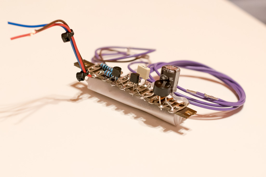
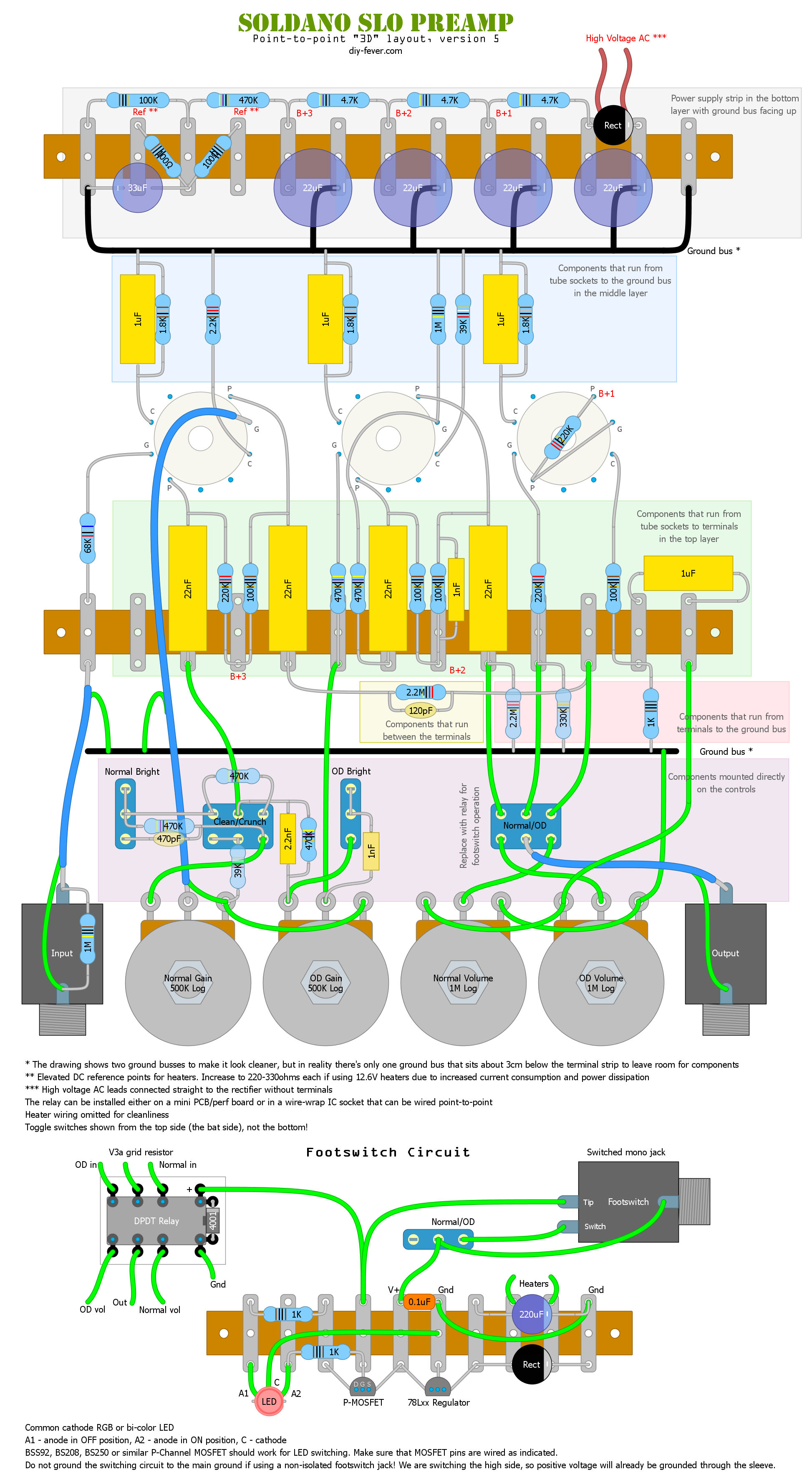
Heaters are powered with 12.6VAC to reduce the current and they are elevated to ~50V. For relay switching I used a relatively simple method. Heater voltage is rectified and regulated to 12V. P-MOSFET is used to drive the multi-colored LED and toggle between two colors designating two main channels. Channels can be switched either using the panel switch or a footswitch.
I intentionally omitted the EQ because I want to use it either with a graphic EQ pedal or connected straight into the interface and have VST EQs applied. It's easy enough to add a shared EQ before the volume pots, slightly more complicated to do dedicated EQs with another DPDT relay.
As far as components go - custom toroidal transformers, alpha pots, russian PIO coupling capacitors, Panasonic HV electrolytics, xicon resistors, miyama switches, JJ tubes, panasonic film 1uF caps for cathodes...
It turned out great. There are no clicks or pops from the relay, voltages are pretty close to the official schematic and noise is very low for a high gain amp. The layout makes it easy to choose between having completely isolated channels or have clean bleed into the overdrive. There doesn't seem to be a big difference but I think I prefer to have them isolated. Connecting two terminals together makes the normal channel always on.
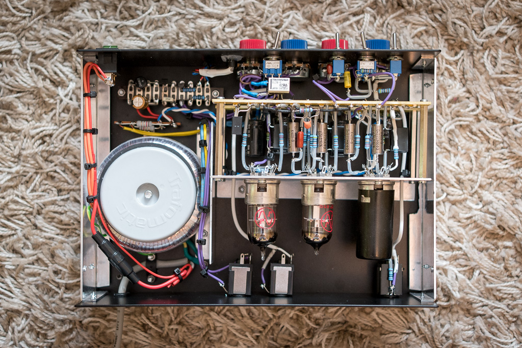
This is how the main module looks assembled. There's one aluminum L profile that holds tube sockets. Using four 50mm hex standoffs I connected two terminal strips with 13 contacts each.
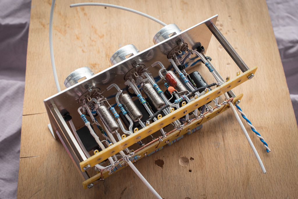
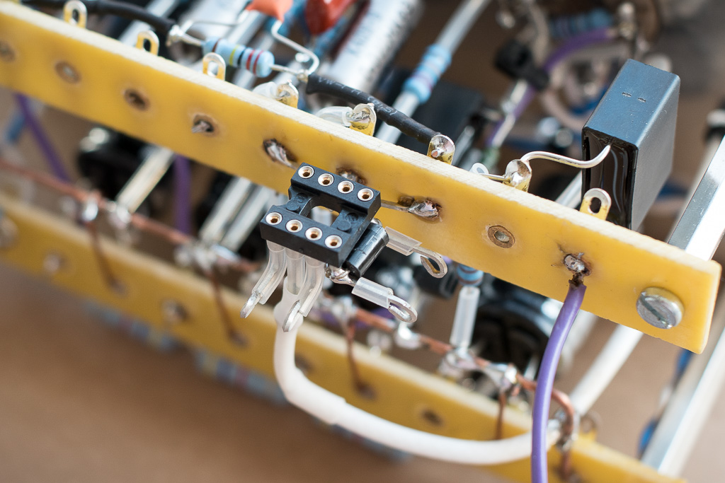
and from the side showing different layers
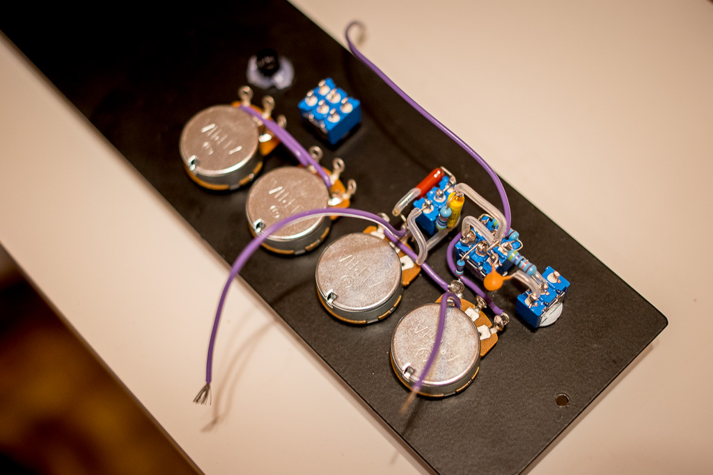
A few components are mounted directly on the controls
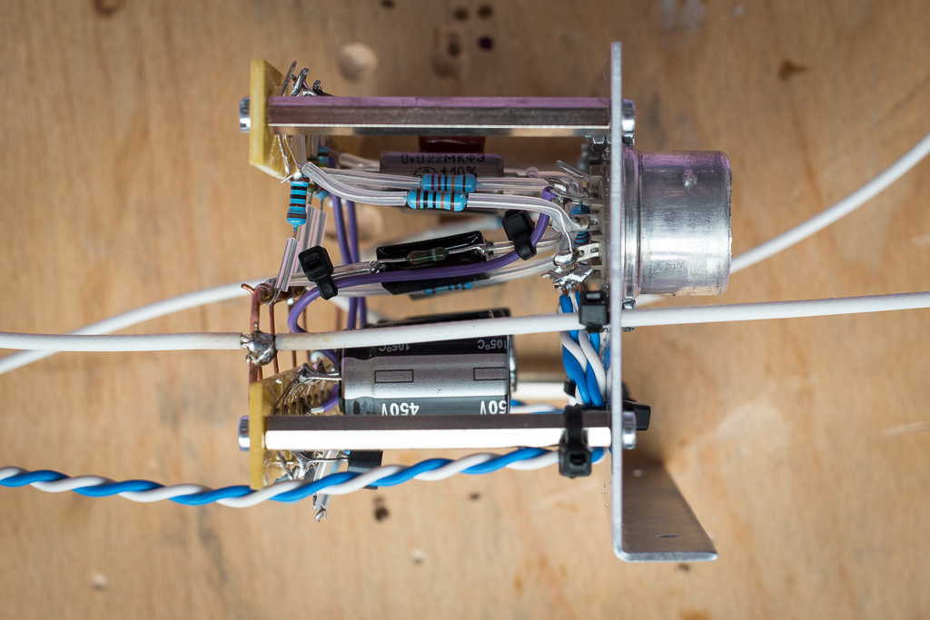
The switching circuit is on a separate terminal strip.
The relay is mounted in a wire-wrap socket soldered directly on the main module
Here's the whole preamp assembled
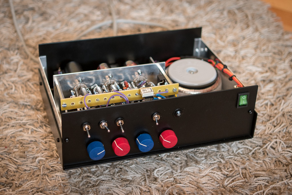
And from the front. Knob color matches the color of the LED - blue for normal, red for overdrive channel.
The article with more pics and info is here http://diy-fever.com/amps/soldano-preamp-mk2/ will update it with more info and clips soon.
Full sized layout here http://diy-fever.com/wordpress/wp-conte ... out_v5.png


