
Thanks for the link. I'll check it out.pdf64 wrote: ↑Sat Jan 25, 2020 6:08 pm Thanks for the DIYLC tip, I've downloaded it before but shied away at first use, when it wasn't immediately intuitive
I'll grit my teeth, knuckle down and try again
Regarding more bias outputs, I'd use Merlin's 'full wave' arrangement (may need to tinker with the R1 value), and have C1 supply parallel sets of the P1, R2, R3 and C2 arrangement http://www.valvewizard.co.uk/bias.html
Channel Switching JCM800 Design? + BIAS pot question
Moderators: pompeiisneaks, Colossal
Re: Channel Switching JCM800 Design? + BIAS pot question
Just plug it in, man.
Re: Channel Switching JCM800 Design? + BIAS pot solved, BUT NOW SCH/DGRM DIFFERENCES!
This 800 build schematic has a 4.7K resistor to ground right after the PI circuit, but it is nowhere to be seen on the diagram. Where do I put this? Is it necessary or optional? The SCH is from 2008, the diagram from 2019.
This 2204 schematic (https://el34world.com/charts/Schematics ... w_2204.pdf) shows R23 as a 4.7k to ground as well.


I looked at the 100W amp schematic they have and the 4.7K resistor is deleted. Is this a personal preference thing? It's fine, I just don't know what difference that would make. Thanks!
This 2204 schematic (https://el34world.com/charts/Schematics ... w_2204.pdf) shows R23 as a 4.7k to ground as well.
I looked at the 100W amp schematic they have and the 4.7K resistor is deleted. Is this a personal preference thing? It's fine, I just don't know what difference that would make. Thanks!
Just plug it in, man.
-
sluckey
- Posts: 3134
- Joined: Sun Jul 22, 2007 7:48 pm
- Location: Mobile, AL
- Contact:
1 others liked this
Re: Channel Switching JCM800 Design? + BIAS pot question
The mojo schematic is WRONG. If your presence pot is 5K you will not be using that 4.7K.
The mojo layout is following the older presence circuit which uses a 5K presence pot. This pot will sound scratchy when turning it because dc current flows through the pot.
The later jcm-800 2204 (as shown in the schematic from el34world) uses a 22K presence pot with a series connected cap which blocks dc current, so the pot does not sound scratchy. However, this circuit REQUIRES the extra 4.7K resistor so the PI cathodes will have a current path to ground.
As for the extra 220K 3W resistor, only mojo knows, but maybe it is intended to be connected across the reservoir cap to drain the charge when switched off. Not a bad idea. However, I would rather install it in the bias circuit between the HT winding and the bias diode.
-
martin manning

- Posts: 13403
- Joined: Sun Jul 06, 2008 12:43 am
- Location: 39°06' N 84°30' W
1 others liked this
Re: Channel Switching JCM800 Design? + BIAS pot question
It's an error in the schematic. Follow the layout, which is the old-style Fender presence. Another way to do it is to place a 4k7 to ground, and in parallel with that a 25k pot in series with the presence cap, which you will see in later Fender and Marshall circuits. I would not use a log pot for the presence. Use a linear taper, unless you can find a reverse log, which is even better.
Re: Channel Switching JCM800 Design? + BIAS pot question
martin manning wrote: ↑Sun Jan 26, 2020 4:54 pm It's an error in the schematic. Follow the layout, which is the old-style Fender presence. Another way to do it is to place a 4k7 to ground, and in parallel with that a 25k pot in series with the presence cap, which you will see in later Fender and Marshall circuits. I would not use a log pot for the presence. Use a linear taper, unless you can find a reverse log, which is even better.
Thanks, guys. Why would you want a scratchy presence pot? Maybe this design intends to point to certain era. I'll design it as is and bench test it to see how it works. If I don't like it, I might need your help rewiring your suggestions. Thanks!sluckey wrote: ↑Sun Jan 26, 2020 4:54 pm The mojo schematic is WRONG. If your presence pot is 5K you will not be using that 4.7K.
The mojo layout is following the older presence circuit which uses a 5K presence pot. This pot will sound scratchy when turning it because dc current flows through the pot.
The later jcm-800 2204 (as shown in the schematic from el34world) uses a 22K presence pot with a series connected cap which blocks dc current, so the pot does not sound scratchy. However, this circuit REQUIRES the extra 4.7K resistor so the PI cathodes will have a current path to ground.
As for the extra 220K 3W resistor, only mojo knows, but maybe it is intended to be connected across the reservoir cap to drain the charge when switched off. Not a bad idea. However, I would rather install it in the bias circuit between the HT winding and the bias diode.
Just plug it in, man.
-
martin manning
- Posts: 13403
- Joined: Sun Jul 06, 2008 12:43 am
- Location: 39°06' N 84°30' W
1 others liked this
Re: Channel Switching JCM800 Design? + BIAS pot question
The frequency response of the old style presence is different, and many people prefer it to the later one.
Re: Channel Switching JCM800 Design? + BIAS pot question
That's the thing, the later version sucks. The control is really only effective for the last half of rotation. The old version is far more effective. The scratching noise sounds like someone blowing across a microphone. It's not bad at all given the usefulness and it's not like your are going to stand there for hours at a time tweaking the knob, being bothered by it
Re: Channel Switching JCM800 Design? + BIAS pot question
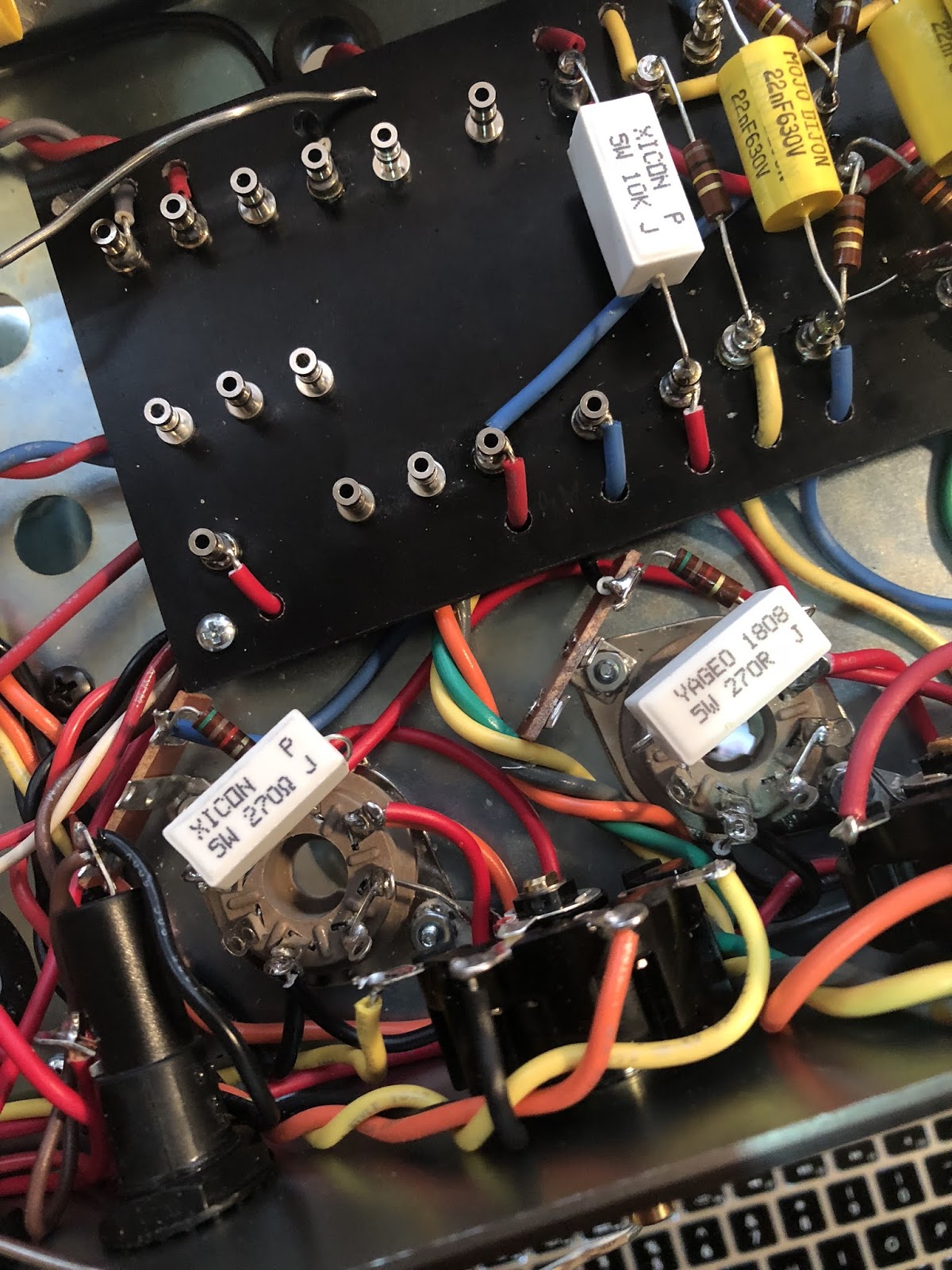
By process of elimination, the “extra” 220K 2W resistor looks to be miscategorized on the layout as a 1/2 W resistor. I’m assuming the 2W version in this scenario would be better. Here’s a picture:
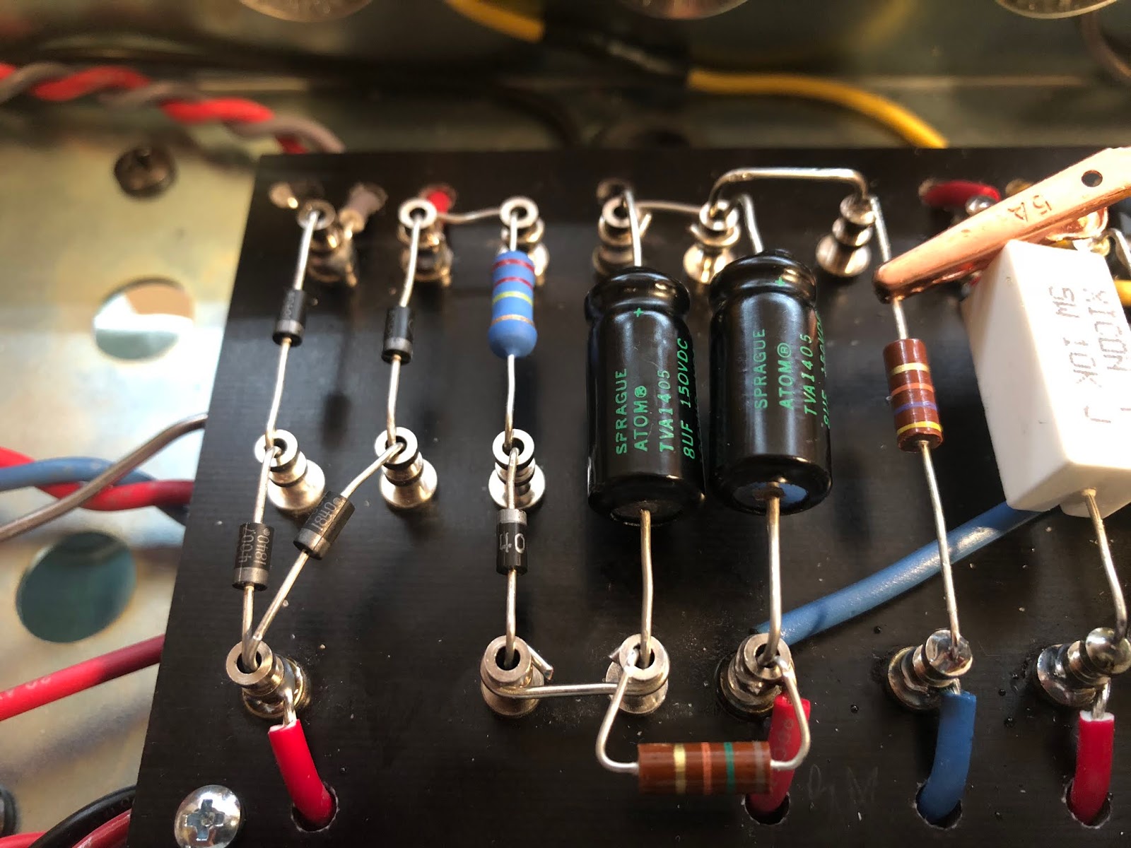
Another thing I noticed is the ceramic resistors spec’d on the power tube socket pins 4-6 are actually 270R and not 1K. I’m assuming that ought to be remedied! Not sure why I overlooked that.
Another thing I noticed is the ceramic resistors spec’d on the power tube socket pins 4-6 are actually 270R and not 1K. I’m assuming that ought to be remedied! Not sure why I overlooked that.
Just plug it in, man.
Re: Channel Switching JCM800 Design? + BIAS pot question
You went with 270Ω for your screen resistors? Is that your choice or did they include the wrong parts in your kit?
Re: Channel Switching JCM800 Design? + BIAS pot question
Wrong parts. The layout and schematic spec 1K 5W so I'll have to change those out. I must have been high on solder smoke to miss that one.
Just plug it in, man.
-
sluckey
- Posts: 3134
- Joined: Sun Jul 22, 2007 7:48 pm
- Location: Mobile, AL
- Contact:
1 others liked this
Re: Channel Switching JCM800 Design? + BIAS pot question
I see another error on the mojo layout. There is a yellow wire labeled "S" that connects a 10K resistor on the board back to the screen node cap can. DO NOT INSTALL THIS WIRE! Doing so will short out that 10K dropping resistor. I can't believe that mojo has released such crappy docs.
-
Colossal

- Posts: 5061
- Joined: Sat Oct 20, 2007 9:04 pm
- Location: Moving through Kashmir
1 others liked this
Re: Channel Switching JCM800 Design? + BIAS pot question
Three guys have come in on 18watt.com in the last couple of weeks, all with untamable squealing on 18W TMB kits. The layout and the drawing is a complete mess. These clowns shouldn't be in business. I bought cabinets from them once. The tolex was peeling in under a month. I bought a 5F8A chassis with poor finish work and sent that back. Lesson learned. Now ViperDoc is getting the wrong parts and a layout full of errors. STEER CLEARsluckey wrote: ↑Sun Jan 26, 2020 9:07 pm I see another error on the mojo layout. There is a yellow wire labeled "S" that connects a 10K resistor on the board back to the screen node cap can. DO NOT INSTALL THIS WIRE! Doing so will short out that 10K dropping resistor. I can't believe that mojo has released such crappy docs.
Re: Channel Switching JCM800 Design? + BIAS pot question
You guys are awesome. The "S" wire essentially creates a loop with the red wire and the 10K dropping resistor. So you would recommend disconnecting that wire?sluckey wrote: ↑Sun Jan 26, 2020 9:07 pm I see another error on the mojo layout. There is a yellow wire labeled "S" that connects a 10K resistor on the board back to the screen node cap can. DO NOT INSTALL THIS WIRE! Doing so will short out that 10K dropping resistor. I can't believe that mojo has released such crappy docs.
I got into mojo at the beginning of my amp-building experiment, and I've had decent success with them. The Bassman and JTM45 amps I just built sound great, although the JTM has quite the hum when you turn it up. Not sure if it's tube related. But these errors are a concern. I'm stuck with what I have, but I appreciate your help. Buying kits seemed like a good idea since I had no experience until a few months ago. Where should I go from here?
FTR, I built a 18 watt TMB combo also and it sounds awesome. I'll have to find if I hear any squeal, that sucker is loud!
Last edited by ViperDoc on Sun Jan 26, 2020 10:31 pm, edited 1 time in total.
Just plug it in, man.
Re: Channel Switching JCM800 Design? + BIAS pot question
Thanks for the info. Where would a green but motivated amp guy go to from here?Colossal wrote: ↑Sun Jan 26, 2020 9:31 pmThree guys have come in on 18watt.com in the last couple of weeks, all with untamable squealing on 18W TMB kits. The layout and the drawing is a complete mess. These clowns shouldn't be in business. I bought cabinets from them once. The tolex was peeling in under a month. I bought a 5F8A chassis with poor finish work and sent that back. Lesson learned. Now ViperDoc is getting the wrong parts and a layout full of errors. STEER CLEARsluckey wrote: ↑Sun Jan 26, 2020 9:07 pm I see another error on the mojo layout. There is a yellow wire labeled "S" that connects a 10K resistor on the board back to the screen node cap can. DO NOT INSTALL THIS WIRE! Doing so will short out that 10K dropping resistor. I can't believe that mojo has released such crappy docs.
Just plug it in, man.
Re: Channel Switching JCM800 Design? + BIAS pot question
Dude, you are off and running and have a great amp build under your belt. You don't need to be buying kits from these tools. They are in it for the money, cutting corners wherever possible. You can source all of the parts, select your own transformers (Heyboer, ClassicTone, Mercury), draw up your layout, and run everything by your friends here. Friends don't let friends get taken. Life is too short for bad tone and needless troubleshooting.ViperDoc wrote: ↑Sun Jan 26, 2020 10:09 pmThanks for the info. Where would a green but motivated amp guy go to from here?Colossal wrote: ↑Sun Jan 26, 2020 9:31 pmThree guys have come in on 18watt.com in the last couple of weeks, all with untamable squealing on 18W TMB kits. The layout and the drawing is a complete mess. These clowns shouldn't be in business. I bought cabinets from them once. The tolex was peeling in under a month. I bought a 5F8A chassis with poor finish work and sent that back. Lesson learned. Now ViperDoc is getting the wrong parts and a layout full of errors. STEER CLEARsluckey wrote: ↑Sun Jan 26, 2020 9:07 pm I see another error on the mojo layout. There is a yellow wire labeled "S" that connects a 10K resistor on the board back to the screen node cap can. DO NOT INSTALL THIS WIRE! Doing so will short out that 10K dropping resistor. I can't believe that mojo has released such crappy docs.