Howdy, guys. I've been thinking about making an ODS preamp in a small pedal format, mostly for use with a cab sim (wife working from home doesn't appreciate the noise).
I'm not really that familiar with Dumbles and the resources here are amazing. I've made a couple tube pedals in the past and was able to put this schematic together thanks to the work done here. Really just looking for any tips, suggestions or picking out mistakes I might have made.
Anyway, the rundown:
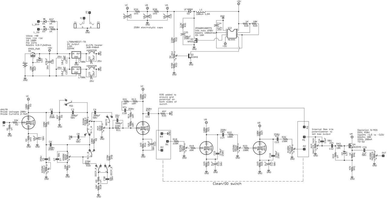
Using 6N17B russian submini tubes
Switch mode power supply for HV from 9V OneSpot plug (1.7A)
6V regulators for the heaters (Thought about running the two tubes in series but I think this will be more stable and reliable)
Output Dumbleator-inspired buffer. My idea here is to use an internal trim pot as the 'Master' control, which feeds the buffer with the Master control that will be on the control panel. I figure if I ever need to push a tube power amp with it, I can just open it up and turn up the internal 'Master.'
Thanks!
Last edited by jubal81 on Sat Feb 27, 2021 10:37 pm, edited 1 time in total.
norburybrook wrote: ↑Thu Jan 07, 2021 8:49 am
cool idea.
Personally I'd go with the high plate values or Bluesmaster. #102 for example, a great well balanced amp.
Looking forward to following this project.
M
Still learning about the different versions, so I'll definitely check those out. I'm thinking I'd prefer something on the cleaner side, with minimal fizz.
I'm also going to have to recalculate the plate and cathode resistors to account for the lower voltages and gain of the submini tube. The datasheet puts them between 60-88, whereas the 12AX7 is about 100.
I was going to use .4w MELF SMD resistors for everything, but I'm going to use through-hole resistors for the plates and cathodes so I can use sockets and tweak them as needed. I saw a Marshall conversion on 18Watt where the builder ended up using higher values, going from 100K/1K5 to 220K/3K9.
Also working on a mockup for the enclosure. It's going in a Hammond 1590XX and I'm going to laser cut some reverse-etch material for the faceplate. I'll drill holes to vent the tubes and use some grill cloth between the enclosure and faceplate to cover them up.
if you take into account the working location of this device (on the floor under your feet), then the concept you showed with the upper location of the ventilation holes and the use of fabric may not be optimal. For such devices, a side ventilation arrangement will be much more practical.
imgrc0077355337.jpg
You do not have the required permissions to view the files attached to this post.
Both are needed IMHO. Heat rises, but air can evade only when new one enters. So side vents for the intake and above for the exhaust - roughly - for me ...
So you don't fear any oscillation issues with such a compact size?
I once had the experience of creating a high-gain preamp in a similar enclosure. On the third attempt, I was able to defeat the problem of the oscillations. I had to optimize the topology of printed circuit boards. By the way, there were no air vents in that case, but I can't say that it was excessively heated. It was slightly warm. And it has been working for 7 years )))
jubal81 wrote: ↑Thu Jan 07, 2021 3:52 pmSomething more like this?
That's better ;^) A couple of people have asked about this concept recently, so there will be interest in how it works out.
Looking at the data sheet, 6N17P are similar to 12AX7's (mu is lower, though, ~65 where you are operating them), and in my experience the boost converter circuit will produce around 280V, so you will also have plate voltages lower than ODS levels. Probably the typical Ra and Rk range seen in ODS variants (100k/1k5 to 220k/3k3) will be ok, though.
I would agree with the above comments on ventilation. For each 400 mA heater you have 2.5W plus 1.2W from the regulator, and 0.3W from each plate. That's almost 9W for the two tubes, plus whatever the source follower and boost converter generate; maybe 10W total? I think I'd put some vents in the bottom (and use rubber feet to raise it up a bit), and a few on each side near the top of the enclosure to get some convection going. Placement would be determined by the internal layout. Regarding the vents, Alkuz1961 has a very good point, if they are on the top and you are going to step on the stomp switches you will be dropping dirt into them.
Bear in mind, these sub-mini tubes are not going to sound the same as 12AX7's. I strongly suggest you breadboard it, so you don't waste time, money and materials and not be pleased with the tone.
I have not tried this, but have spoken with those who have, and these tubes have proven to sound (particularly when in overdrive) substantially different than a more traditional tube type.
jubal81 wrote: ↑Thu Jan 07, 2021 3:52 pmSomething more like this?
That's better ;^) A couple of people have asked about this concept recently, so there will be interest in how it works out.
Looking at the data sheet, 6N17P are similar to 12AX7's (mu is lower, though, ~65 where you are operating them), and in my experience the boost converter circuit will produce around 280V, so you will also have plate voltages lower than ODS levels. Probably the typical Ra and Rk range seen in ODS variants (100k/1k5 to 220k/3k3) will be ok, though.
I would agree with the above comments on ventilation. For each 400 mA heater you have 2.5W plus 1.2W from the regulator, and 0.3W from each plate. That's almost 9W for the two tubes, plus whatever the source follower and boost converter generate; maybe 10W total? I think I'd put some vents in the bottom (and use rubber feet to raise it up a bit), and a few on each side near the top of the enclosure to get some convection going. Placement would be determined by the internal layout. Regarding the vents, Alkuz1961 has a very good point, if they are on the top and you are going to step on the stomp switches you will be dropping dirt into them.
Sounds good. Thanks!
Good point on the ventilation, guys. I'll add some ventilation on the sides, at least. I'd thought about protecting the interior from dirt and dust (we have 3 dogs), which is why I've been considering using grill cloth on the vents.
FUCHSAUDIO wrote: ↑Mon Jan 11, 2021 4:27 pm
Cool concept, I like the layout.
Bear in mind, these sub-mini tubes are not going to sound the same as 12AX7's. I strongly suggest you breadboard it, so you don't waste time, money and materials and not be pleased with the tone.
I have not tried this, but have spoken with those who have, and these tubes have proven to sound (particularly when in overdrive) substantially different than a more traditional tube type.
Oh, that's interesting. Hadn't heard that before. My only previous experience with these tubes was using them for a Matchless Chieftain preamp in a 125B pedal format. I had to use a boost to get it to distort, but I didn't notice it sounded different that what I expected from tube distortion. Though I've never done a true apples-to-apples test.
Looking at this project as an experiment to tinker around with at home. If I can't get it sounding good enough with subminis, I'll switch gears. Thanks for the heads-up, though.
alkuz1961 wrote: ↑Sat Jan 09, 2021 9:12 am
I once had the experience of creating a high-gain preamp in a similar enclosure. On the third attempt, I was able to defeat the problem of the oscillations. I had to optimize the topology of printed circuit boards. By the way, there were no air vents in that case, but I can't say that it was excessively heated. It was slightly warm. And it has been working for 7 years )))
Care to share how you optimized?
"Education is what you're left with after you have forgotten what you have learned" - Enzo
dorrisant wrote: ↑Mon Jan 11, 2021 8:58 pm
Care to share how you optimized?
I had to make several variants of the PCB, changing the location of components and ground points. The photo shows one of the intermediate working devices.
P1040769.JPG
You do not have the required permissions to view the files attached to this post.