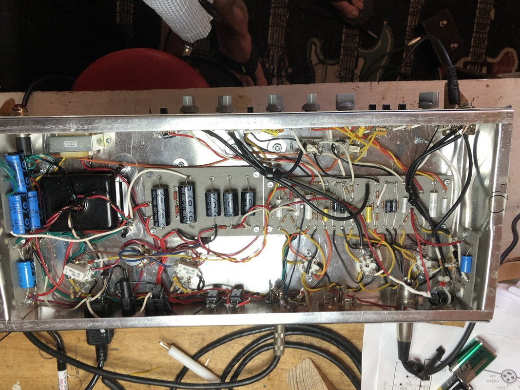
Now I have power straightened out. B+ flowing through all nodes (except the FET board is disconnected), plenty of negative bias voltage and heaters at every tube socket.
My next step is to install preamp tubes and use my fancy test equipment to trace the circuit from input jack to power tubes pin 5. Here’s my signal generator:
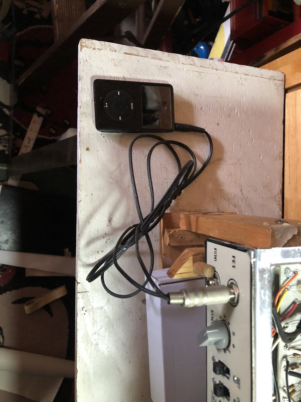
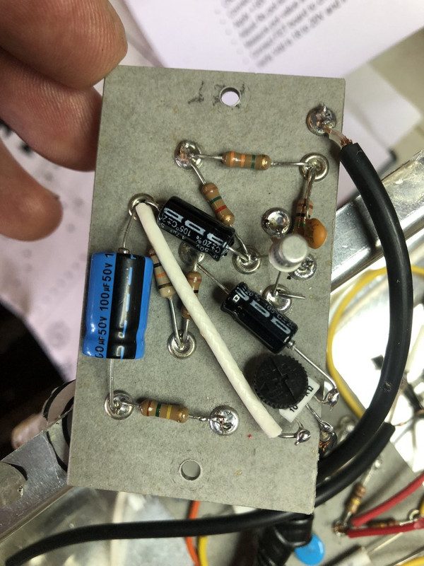
And here’s my signal tracer:

It’s a pen body with a coupling cap inside soldered to a nail. The shield connects to the alligator clip to the chassis and the lead goes to a plug. I plug it into a mini Marshall amp that I broke the volume knob off of, so it’s always at full volume (like any Marshall should be). So put you schematic and layout in front of you and trace the signal through each tube and control. The problems are obvious - where the signal stops, you screwed up. You can also check that each volume and tone control works as expected. Because the foot pedal isn’t hooked up yet, I’m using the front panel manual switch to engage the overdrive.
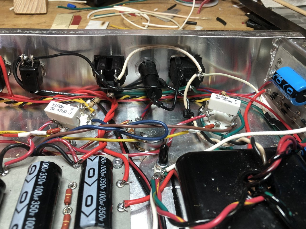
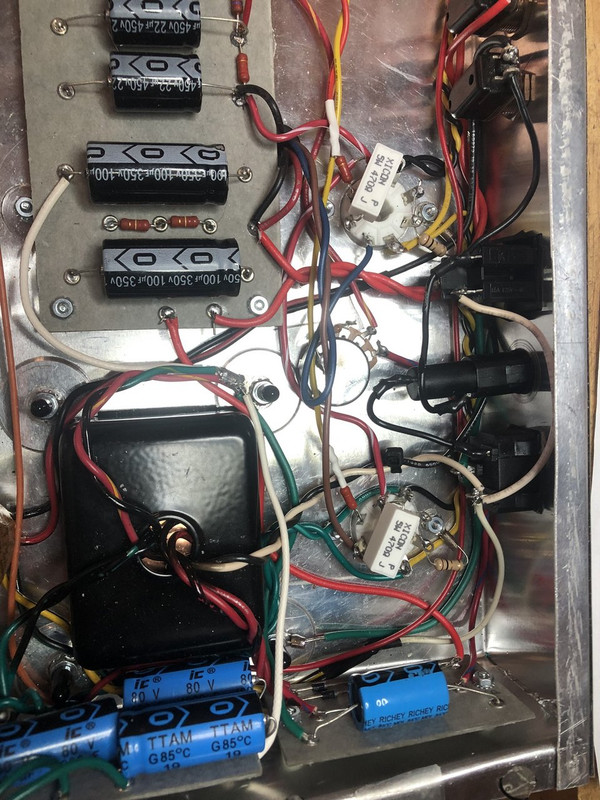
I found surprisingly few problems tracing through the circuit. A bad wire with an intermittent short. I screwed up the polarity on the relay power line. I chopsticked the hell out of the circuit and found a few shitty solder joints. Otherwise, right on plan.
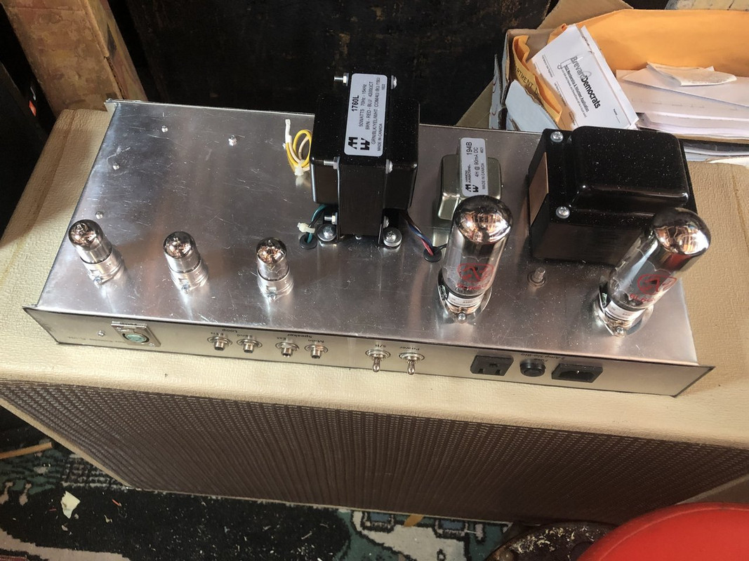
Time to install power tubes. At this point, you have to hook up to a speaker cab (or other load) to avoid killing you OT.
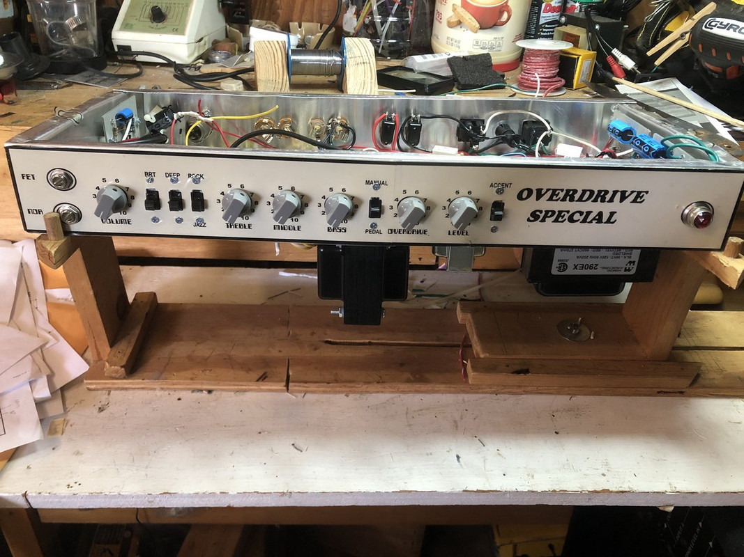
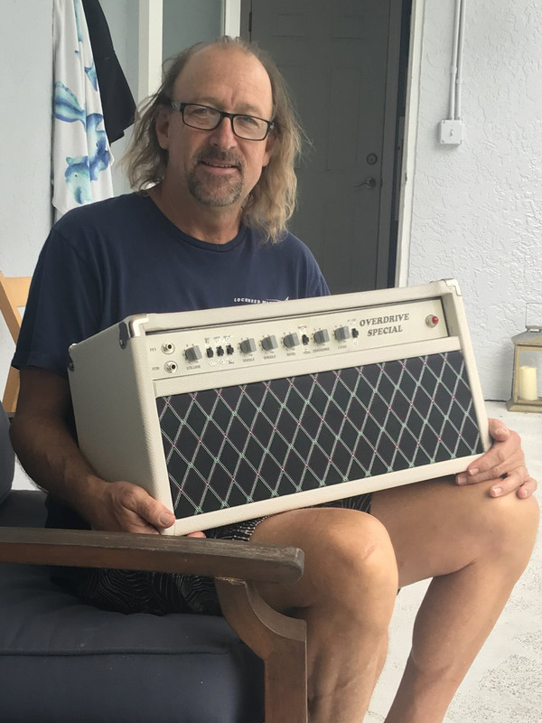
Always a dramatic moment. Flip the switch and… No hum, no buzz, no hiss. But it is alive! It works, it’s loud and all basic controls work as I expect. I’ll assess tone and nuances later, but I have a working amp.
I tweaked the bias from max cold (27.4) to 40/43. I’ll fine tune that later.
Now it’s time to consider next steps.