 1728]http://theinside.net/FLR/r1.JPG[/img]
[img
1728]http://theinside.net/FLR/r2.JPG[/img][img
1728]http://theinside.net/FLR/r3.JPG[/img][img
1728]http://theinside.net/FLR/r4.JPG[/img][img
 1200]http://theinside.net/FLR/r5.JPG[/img]
[img
1728]http://theinside.net/FLR/r6.JPG[/img][img
1728]http://theinside.net/FLR/r7.JPG[/img][img
1728]http://theinside.net/FLR/r8.JPG[/img][img
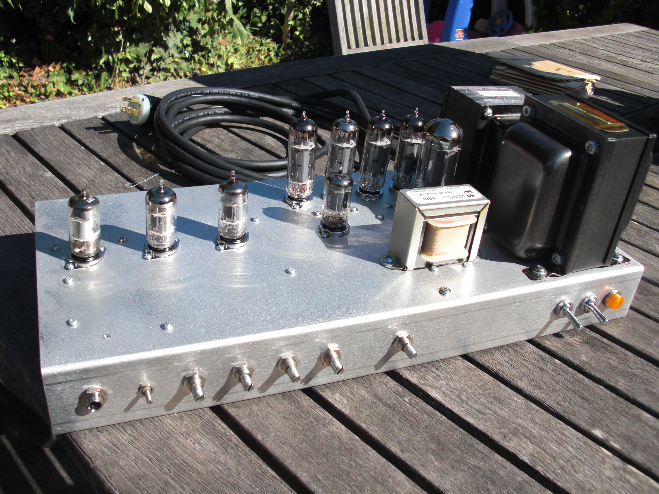
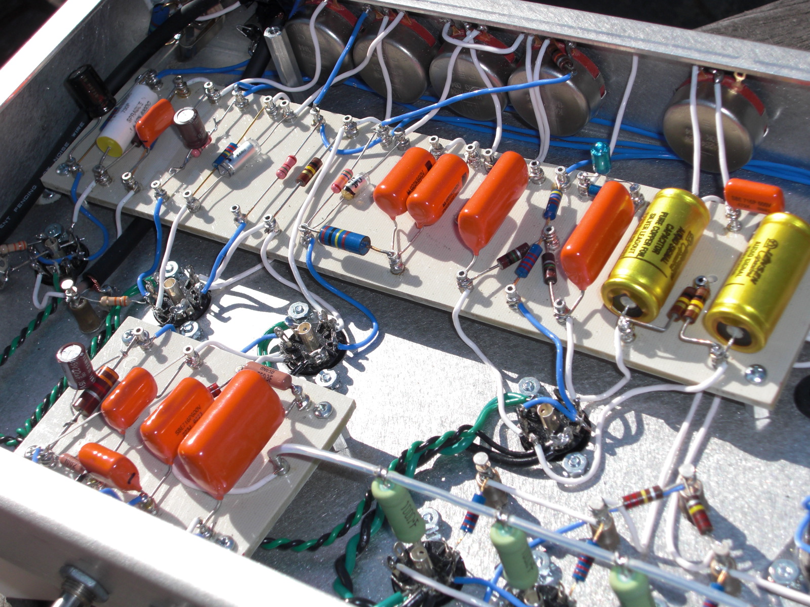
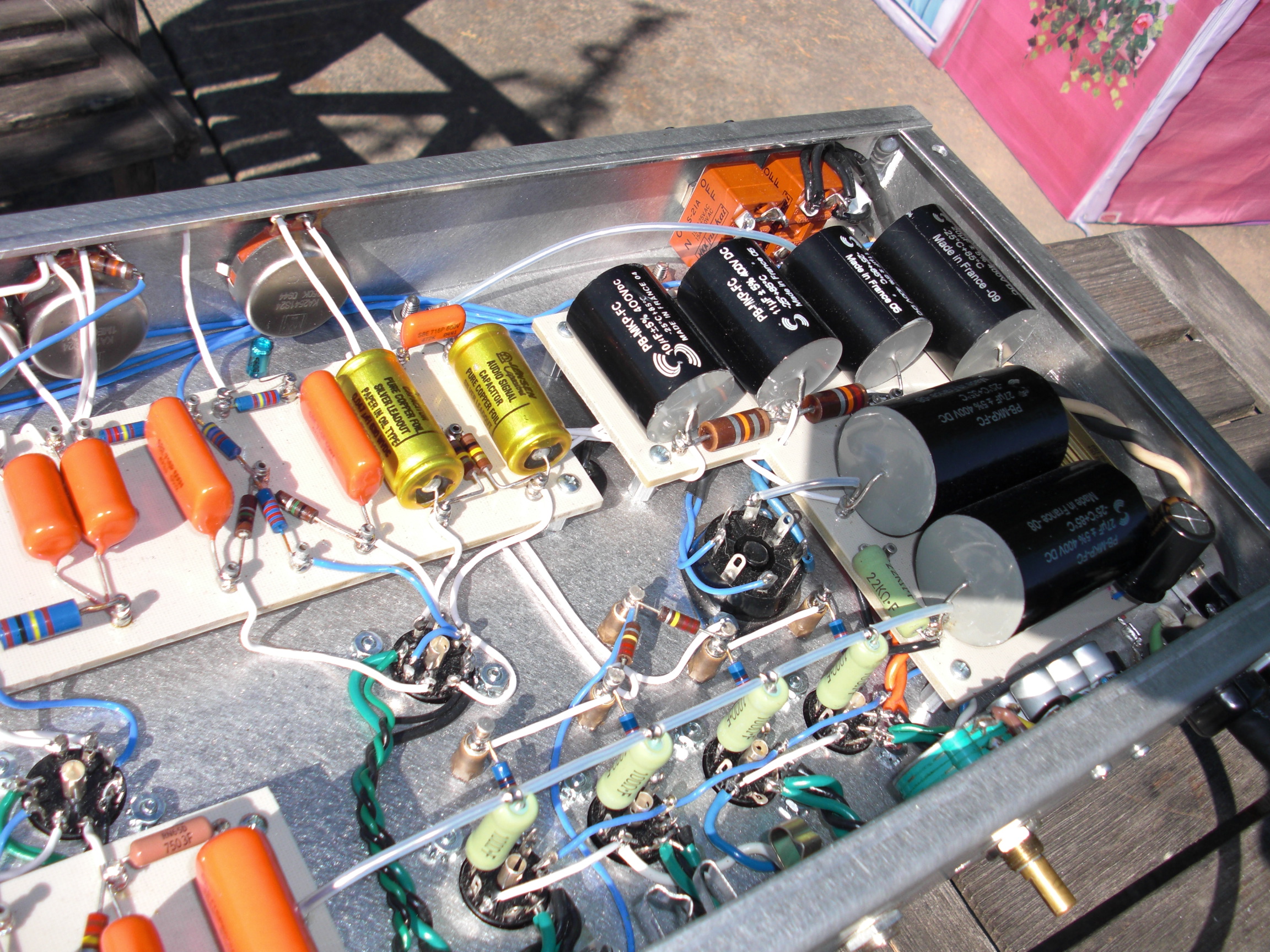
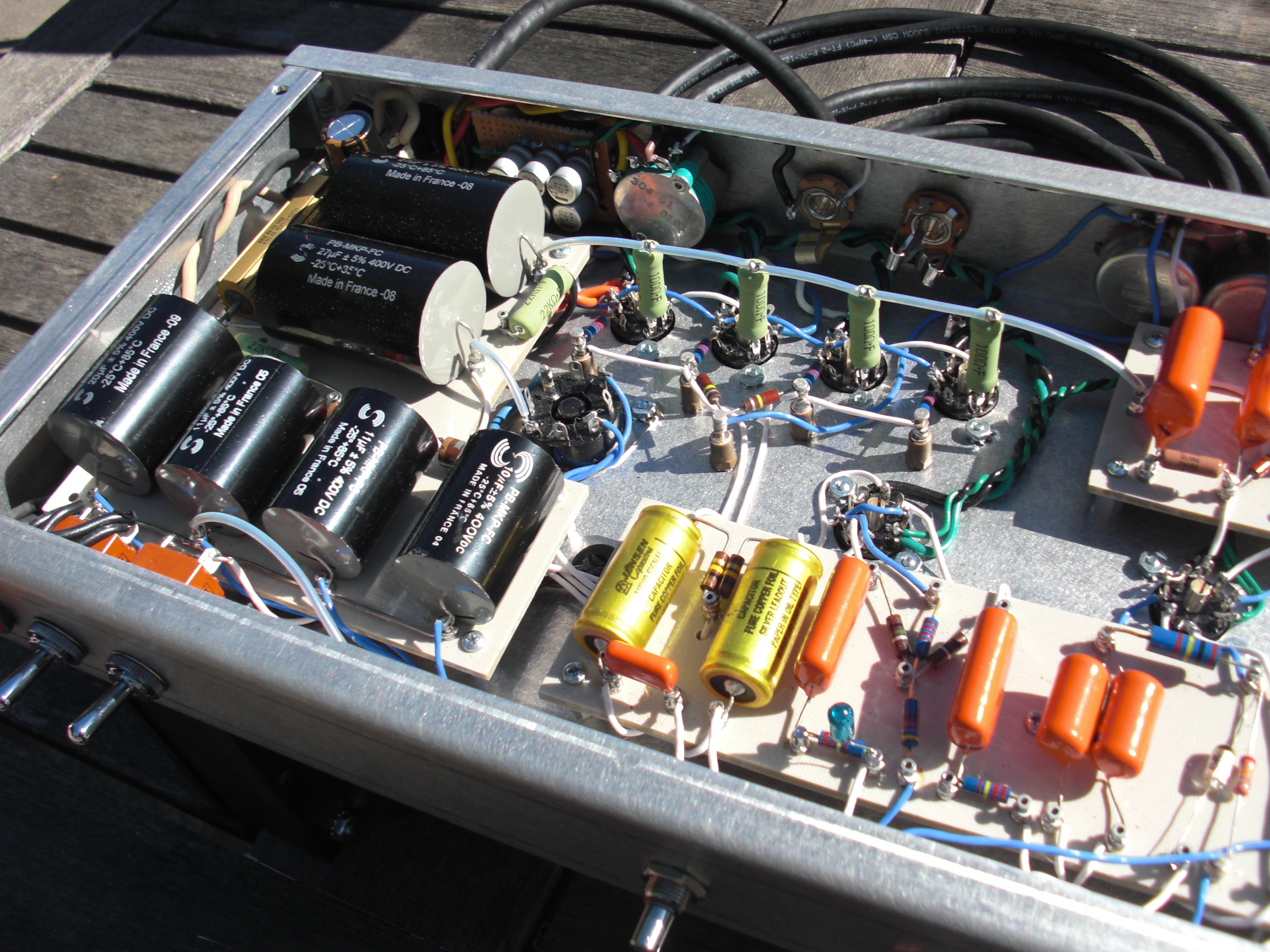
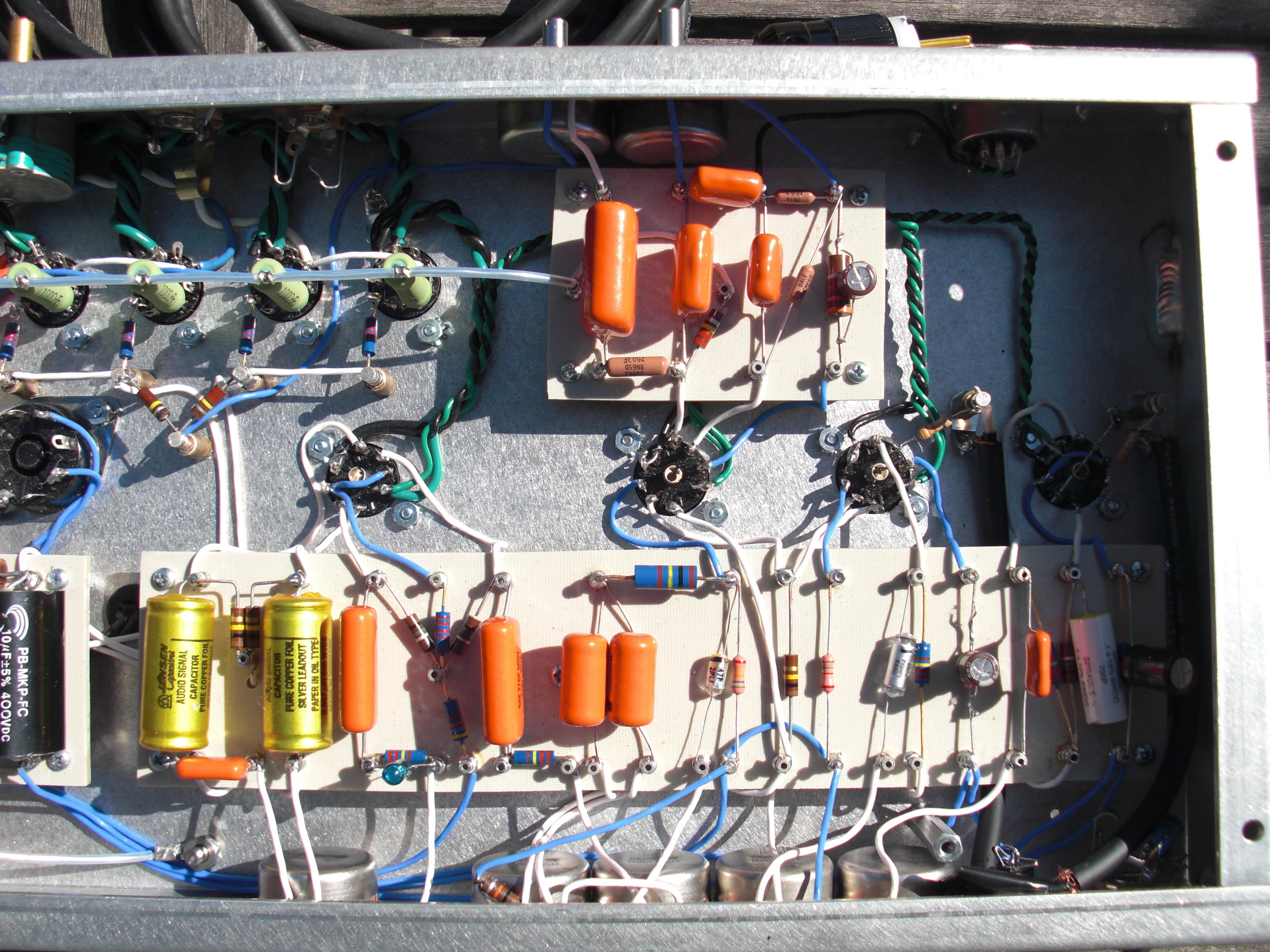
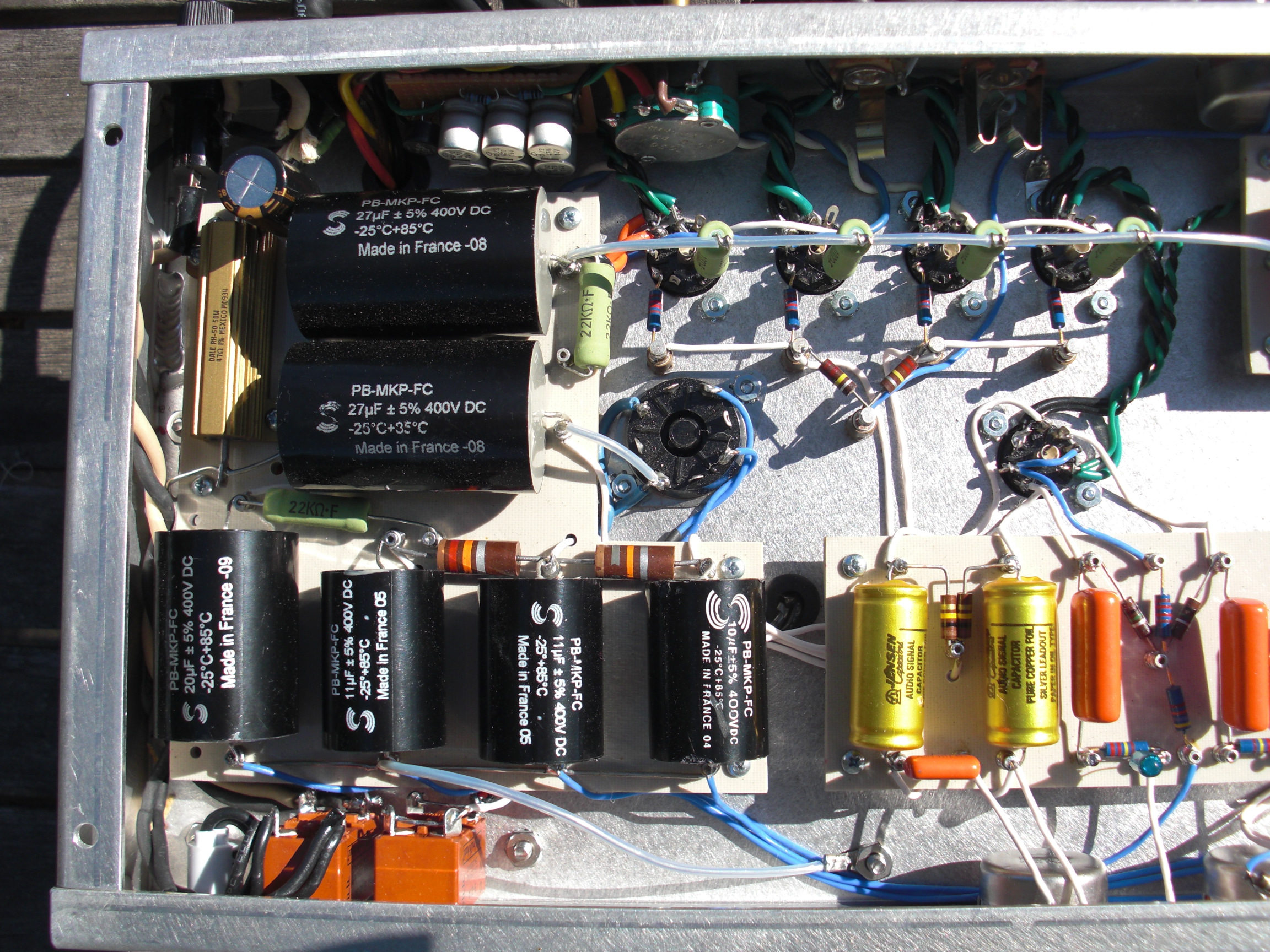
1728]http://theinside.net/FLR/r9.JPG[/img]This will somewhat answer the question as to how much can fit into the standard size chassis! It's two channels, top boost and EF86, with bias modulated tremolo. What's not installed yet are the three relays to switch channels, select both channels in parallel, and cascade the EF86 output into the top boost channel for a high gain overdrive.
I've just about got the overdrive network worked out, as the EF86 channel is pretty thick and needs a bit of eq. The relays are going between the input and the first volume control, so the wiring is tight and I need to tweak first. I fired it up the first time on Thursday, just the top boost. Friday I just wired both channels to the input and went to band practice. I can probably get some clips posted a bt later. The EF86 sounded pretty bad, just using the vox values at 266 volts. I needed to up the dropping resistor on the screen to 1.2 meg and lower the coupling cap to .0022 and it's still got a bigger bottom, low mid than the top boost.
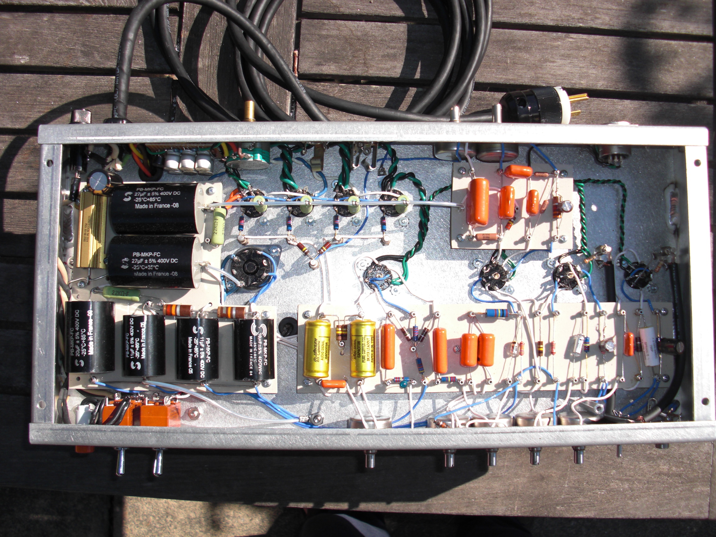
I also went with much lower power supply filtering, 27 on the plates, 27 on the screens (biggest cap that would fit!), 20 off the screen for the EF86, 11 also off the screen for the PI, then on to 11 and 10 for the top boost tubes. I'm trying to get more of a vintage vox sound, I suppose. I'm also using different dropping resistors, although I haven't gotten into tweaking the voltages much, yet. 22k to the PI, 11k to the second gain stage, and I think 18k to the first stage.
There are two interesting aspects of the rocket I read somewhere on the internet.
The first is that Ken told someone the gain stages in the rocket preamp are biased in class A2. I think this is in the blue guitar threads. So, that would mean the first gain stage's grid was drawing current. Of course, how is that possible when it's just connected to the guitar. Anyway, in the course of building this phono preamp I was doing with big plate loads and low voltages, there was talk that when you run a 12ax7a at low voltages, say below 80 volts, electrons would begin to collect on the grid developing a small voltage. The voltage at which the current would happen varied from tube to tube, though. Their advice for the phono preamp naturally was to not run the tubes below 80 volts to avoid the distortion and lower impedance of that situation. However, it took a while, but I thought that must be the key to how Ken could get the preamp to something resembling class a2. That's also what I was going for in using bigger dropping resistors. When I was screwing around with voltages on the second stage with direct coupled cathode follower biased with a 56k, it seemed like just over 100 volts on the plate of v2 is where a voltage, negative, started developing on the grid. My v1 plate is around 74 volts and it's got a bigger negative voltage on the grid. We're talking 20-30 milivolts though. Not a big deal, but kind of interesting. That was a tungsram tube.
The other thing I remember reading, this has probably been discussed before, is that Ken would present the amp to the customer with an optional resistor which he would clip out if the customer liked the tone better without. That it sounded like "peeling away a layer of harmonics." It looked like there were some Rocket schematics floating around with two 1.5k's in parallel at the cathode of the PI. I did a bit of tweaking there and lower values, 820-910 did seem to bring out a harmonic centered around the fundamental. Struck me as bit too much, but it's an area that may need some more experimentation!


