
Hi Vertigo,
this is due to the original Japanese schematic which calls for a 60uF. After some research we found that Sprague had 60uF electrolytics during 70-ies and 80-ies.
A double 33uF is close enough and will tighten the feel and response of the bass in the amp.
Ryan & Erwin's SSS #002 Madness
Moderators: pompeiisneaks, Colossal
-
martin manning

- Posts: 13360
- Joined: Sun Jul 06, 2008 12:43 am
- Location: 39°06' N 84°30' W
Re: Ryan & Erwin's SSS #002 Madness
This was brought up in the schematic review on page 5 of this thread. In the hand drawn schematic a 60u is shown on the PI node. Member Richard1001 suggested that it should have been on the screen node. That may be true, since the screens draw transient current when the power stage is driven hard, and the screen node also supplies the reverb driver branch. IMO a 47u would be fine there, as Richard used on his build.

Re: Ryan & Erwin's SSS #002 Madness
Thank you Erwin and Martin. I saw the discussion about the zener diode and the filter switches but seemed to have missed the one about the power supply.
Sean Chaney

Re: Ryan & Erwin's SSS #002 Madness
I just finished helping someone with a very similar issue. It turned out to be a melted coax cable. Try unsoldering the ground of the coaxes one by one and see if this improves. Also, try plugging a source signal into the power amp input on the back to see if it's your preamp or power ampMichiel ODB wrote: ↑Mon Sep 28, 2020 6:03 pm Hi all,
Almost done with my version of the SSS!Made chassis & boards by myself and the pre amp is already sounding beautifull!
However, some problems come up in the power stage, I think it might have to do something with my PI. Maybe some guru's in here can assist me with my problem, cause I'm almost out of options, (First time on this forum also, so if this isn't the right place to ask for help, please let me know!
)
I will try to explain my problem as clear as possible.
The sound I'm getting out of the amp is very weak at full volume, and way too distorted. When I put my scope on the output of the power tubes, I can see the original signal, but also a lot of ripple and unwanted behaviour. I'm guessing al this extra 'noise' Is cancelling out the actual sound in the output trannie ... (not really sure of noise is the best way to describe it btw)
When I add a clean sinus signal on the input of the PI (say 440Hz, about the same magnitude as I would normally have on the end of the pre amp), I can trace it with my scope, all the way up to pin 2 of the first valve (V5, in Ryan and Erwin's github schematic). However, on pin 1, the signal is "wobbles" all over my scope screen. I Think it might have to do something with a ripple on the supply voltage that reaches the trimpot (D, in the schematic), but than I would expect the same behaviour on the other first pins in the amp, but the preamp just sounds fine.
Some ideas?
Already rebuild the PI and power section, have the right voltages on all tubes, and the output trannie seems to be fine.
(note: the picture from above is before I re-did some components, so some wiring might look different in the other pic)
Ryan
https://www.thetonegeek.com/
https://www.thetonegeek.com/
Re: Ryan & Erwin's SSS #002 Madness
Erwin, what's the purpose of the 3K3 5W resistor on the back of your multi cap can going into the terminal strip? I can't see that it goes anywhere
Sean Chaney
-
bentmlaing
- Posts: 1
- Joined: Sat Sep 19, 2020 11:13 pm
Re: Ryan & Erwin's SSS #002 Madness
Yo-
What are the dimensions of the Preamp board and the PI board?
Posted public as I figured others have already built this-
Cheers-
What are the dimensions of the Preamp board and the PI board?
Posted public as I figured others have already built this-
Cheers-
Re: Ryan & Erwin's SSS #002 Madness
In the github file, that Ryan made, are the pdf of each board.bentmlaing wrote: ↑Wed Oct 14, 2020 10:25 pm Yo-
What are the dimensions of the Preamp board and the PI board?
Posted public as I figured others have already built this-
Cheers-
With a pdf viewer the size of each board should pop up.
https://github.com/colganr/steel-string ... and%20PDFs

Re: Ryan & Erwin's SSS #002 Madness
Hey, buddy
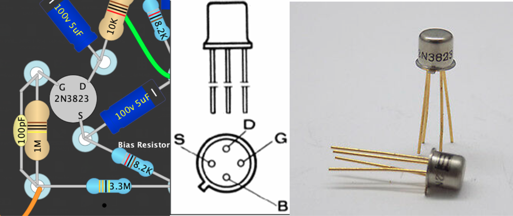
Can anyone help me, as for the fourth pin "B" of 2N3823 should be soldered where?
Thanks
Can anyone help me, as for the fourth pin "B" of 2N3823 should be soldered where?
Thanks
-
martin manning
- Posts: 13360
- Joined: Sun Jul 06, 2008 12:43 am
- Location: 39°06' N 84°30' W
Re: Ryan & Erwin's SSS #002 Madness
Ground. It's connected to the metal case.
-
Michiel ODB
- Posts: 3
- Joined: Mon Sep 28, 2020 4:06 pm
Re: Ryan & Erwin's SSS #002 Madness
Hi again, sorry for the late respons but I was kind of busy, just started at my first job so I had to leave this amp for a weeksrccolgan wrote: ↑Thu Oct 08, 2020 9:42 pmI just finished helping someone with a very similar issue. It turned out to be a melted coax cable. Try unsoldering the ground of the coaxes one by one and see if this improves. Also, try plugging a source signal into the power amp input on the back to see if it's your preamp or power ampMichiel ODB wrote: ↑Mon Sep 28, 2020 6:03 pm Hi all,
Almost done with my version of the SSS!
However, some problems come up in the power stage, I think it might have to do something with my PI. Maybe some guru's in here can assist me with my problem, cause I'm almost out of options
I will try to explain my problem as clear as possible.
The sound I'm getting out of the amp is very weak at full volume, and way too distorted. When I put my scope on the output of the power tubes, I can see the original signal, but also a lot of ripple and unwanted behaviour. I'm guessing al this extra 'noise' Is cancelling out the actual sound in the output trannie ... (not really sure of noise is the best way to describe it btw)
When I add a clean sinus signal on the input of the PI (say 440Hz, about the same magnitude as I would normally have on the end of the pre amp), I can trace it with my scope, all the way up to pin 2 of the first valve (V5, in Ryan and Erwin's github schematic). However, on pin 1, the signal is "wobbles" all over my scope screen. I Think it might have to do something with a ripple on the supply voltage that reaches the trimpot (D, in the schematic), but than I would expect the same behaviour on the other first pins in the amp, but the preamp just sounds fine.
Some ideas?
Already rebuild the PI and power section, have the right voltages on all tubes, and the output trannie seems to be fine.
(note: the picture from above is before I re-did some components, so some wiring might look different in the other pic)
Re: Ryan & Erwin's SSS #002 Madness
Hi Dumble Gurus,
I'm reading this and other SSS related threads for quite a while now. A friend of mine, a professional guitar player, dreams of a SSS and I was building tube amps for years (and being a lousy bass player). We are going to start the project (hopefully) soon but there is one understanding issue I have and I didn't find any explanation on this so far. I hope my english is good enough to pinpoint the issue and understand the responses...
I'm referring to the schematic of Martin on page 7 (the issue starts with the japanese hand drawn schematic already)
I never understood, why there are the resistors (in Martin's schematic) R31/32 and R 47/51. The topology of the SSS bias circuit is similar to other amps like the Ampeg SVT, some Fender bass ams and others. None of the others have these resistors, all feed the cathode of the driver directly to the grids of the power tubes. Why are they in here? Is there a technical reason? What would happen, if they were omitted?
I can't do a simulation myself, maybe someone would check it?
Thanks
Robert
-
martin manning
- Posts: 13360
- Joined: Sun Jul 06, 2008 12:43 am
- Location: 39°06' N 84°30' W
Re: Ryan & Erwin's SSS #002 Madness
That schematic didn't originate from me, but those resistors are a curiosity. The 002 has 220k cathode resistors, and two 470k in parallel to ground.On the 001's schematic, the cathode resistors are 100k, and the 470k resistors do not appear. On the 002 I suspect they are there to reduce the negative voltage on the cathodes of the driver tube when the amp is in standby, another consequence of the negative voltage being derived from the HT. A single 235k on each side would have done the same thing, so I don't know why there are two.chaccmgr wrote: ↑Thu Nov 05, 2020 12:55 pmI'm referring to the schematic of Martin on page 7 (the issue starts with the japanese hand drawn schematic already)
I never understood, why there are the resistors (in Martin's schematic) R31/32 and R 47/51. The topology of the SSS bias circuit is similar to other amps like the Ampeg SVT, some Fender bass ams and others. None of the others have these resistors, all feed the cathode of the driver directly to the grids of the power tubes. Why are they in here? Is there a technical reason? What would happen, if they were omitted?
-
Richard1001
- Posts: 254
- Joined: Tue Oct 23, 2007 6:12 pm
1 others liked this
Re: Ryan & Erwin's SSS #002 Madness
While installing my chassis in a cabinet i noticed that reversing the polarity of the reverb drive signal results in lower noise on the reverb return.
Maybe this is usefull to some. My cabinet is lower than original and i had some hum with the return pot on full. Reverse polarity of the drive signal fixes this.
I had wondered why the polarity of the drive signal was reversed on the japanese schematic, and now i know...
Maybe this is usefull to some. My cabinet is lower than original and i had some hum with the return pot on full. Reverse polarity of the drive signal fixes this.
I had wondered why the polarity of the drive signal was reversed on the japanese schematic, and now i know...