I ran into some issues using my EP3 echoplex into the second input of my Marshall since I found it flips the phase of the signal 180. Normally never an issue, but because I split the signal to input one and then to the EP3 then input 2, there tends to be phase cancellation.
Sooo... I built an Op-amp phase inverter in a little box. Works great! Did what I wanted. BUT, I'm not up on my circuit knowledge and only designed this with the bare minimum of parts.
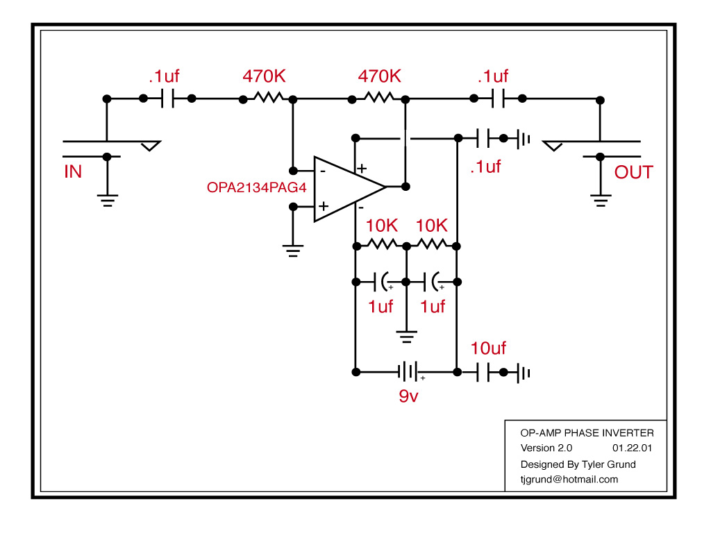
I'm wondering if anyone would have any suggestions of additional circuit changes that might improve the fidelity or performance of the circuit. Such as coupling caps, or such. Thanks!
[img
 768]http://www.tylergrund.com/images/opamp_ ... r_v1.0.jpg[/img]
 613]
613]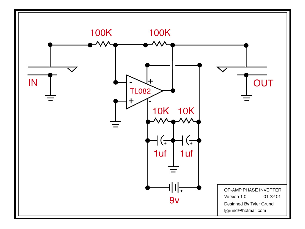