Mark wrote: ↑Mon Jul 08, 2019 8:05 am
How was the bass response affected by the change in screen voltage?
Not much since I replace a choke with a 420R resistance with a 470R resistor. the CLC filter and increased filtering matters more. A smaller screen resistor gave a nasty tone I didn't care for. too little screen resistance resulted in some strange distortion I didn't like.
Roe,
I imagine your amp to be very quiet with the CLC in front of B+1. Very low ripple. With just the traditional setup of 16uF for the reservoir cap, the ripple is 10V pk-pk. 32uF cuts that down to 5V pk-pk. Did you notice a change in feel or dynamics going to the CLC supply?
That's an interesting observation about the smaller screen dropping resistor giving bad tone.
Its extremely quiet for an ac30. and the bass is tighter and bolder than you'd expect. however, the feel or dynamics is roughly the same as an ordinary ac30 with somewhat higher filtering. but its not too stiff with 33uf at the screens. the big HAMMOND 5h 300ma choke has a resistance similar, but a little, lower than a gz34.
in this case, too much screen voltage and current seem result in (crossover?) distortion. A different thread here discussed a similar phenomenon on typical fender/dumble style output amps with small 470R screen resistors
Roe wrote: ↑Mon Jul 08, 2019 1:28 pm
Its extremely quiet for an ac30. and the bass is tighter and bolder than you'd expect. however, the feel or dynamics is roughly the same as an ordinary ac30 with somewhat higher filtering. but its not too stiff with 33uf at the screens. the big HAMMOND 5h 300ma choke has a resistance similar, but a little, lower than a gz34.
Oh, I bet it is extremely quiet. That CLC arrangement is tempting but I was concerned it might take away too much. I am using 32-2k2-32uF on an 18W and it is very quiet and pleasing under the fingers. I am happy to be rid of PS hum though so an increase in filtering is definitely in order.
in this case, too much screen voltage and current seem result in (crossover?) distortion. A different thread here discussed a similar phenomenon on typical fender/dumble style output amps with small 470R screen resistors
I will try a 10 and 20H choke and stick with 100R screen resistors to start. With 300V plates or so, a 10H choke will drop about 5V and the typical Vox 20H about 9V.
I've put the standoff for the heaters in and it pretty much time for the power transformer to go in.
This leads me to revisit what fuses should be added to ensure a fault doesn't take out the transformers and the choke. The initial fuse that comes to mind is a fuse between the valve rectifier and the first filter cap. I will also put solid state diodes inline with the valve rectifier for additional protection in case the rectifier goes bad. The other areas to fuse might be the 6.3vac and the 5vac taps, but what concerns me is inrush current blowing these fuses.
I will also have to pay attention to earthing. Where to earth the 6.3 heater centre tap and the secondary centre tap.
I'm wanting get the output stage together and see what the rail voltage will be and how badly hammered the EL-84 are getting. I'll trying getting a sound out of it by sticking it on the backend of my 18 watter.
Mark wrote: ↑Thu Jul 11, 2019 12:07 amI will also have to pay attention to earthing. Where to earth the 6.3 heater centre tap and the secondary centre tap.
I'm wanting get the output stage together and see what the rail voltage will be and how badly hammered the EL-84 are getting. I'll trying getting a sound out of it by sticking it on the backend of my 18 watter.
Any thoughts?
Hi Mark,
Regarding grounding and the secondary and heater center taps...I prefer to ground the HV secondary center tap right at B+1's negative terminal (or supporting turret or eyelet). I try to keep AC rectification and B+1's cap in a physically small loop and located as physically far from the signal side as possible. Since rectification is tube in this case, then I would locate B+1 reservoir cap close to the socket and return the HV center tap to B+1's ground. That should make for a tight loop. I saw the way Greg Fryer ran his ground leads to a common star point. These days, I have been using a single chassis point ground for the IEC mains earth connection and then one ground right near the guitar input jack. Everything in the amp grounds to a rail, in sequence on down the line, and then that rail ties to that single ground point at the input. As for the heater center tap, I am a believer in heater elevation to DC, usually providing a dedicated voltage divider and small cap off the main B+ rail and then tying the heater center tap to that cap, or, you could tie to the power tube cathodes and get +10-12VDC there for free. I usually prefer to go higher though, 50V or so, especially with any amp with a cathode follower (if you are using the Top Boost circuit). The Top Boost cathode follower runs the cathode pretty hot, 100VDC if I recall correctly, which is right at the published heater-to-cathode limit for modern production 12AX7s, so a good 50VDC offset will help that. Old tubes used to be able to handle 200V h-k. I have been building very quiet amps using these methods. I don't do multiple chassis ground points any more, unless it is say a Marshall clone and then I do the generally recognized five point scheme.
The chassis is a stock AC-30 chassis and I'm not able or prepared to cut up the chassis to move stuff around. I think that is best suited to a blank chassis where the layout is still on paper.
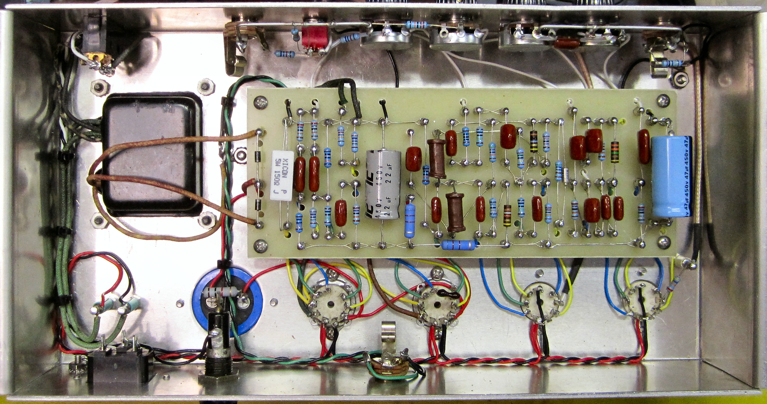
IMG_1009.JPG
You do not have the required permissions to view the files attached to this post.
It is still simple to 'return the HV center tap to B+1's ground' (ie the Reservoir cap's -ve terminal), then connect that to the chosen power amp chassis' 0V common return point.
Rather than having physically separate chassis 0V connections for the HT winding CT and the reservoir cap's -ve terminal, as that would 'pollute' the chassis unnecessarily with the heavy ripple current that would then flow between those 2 points.
However, sometimes an amp can be 'thrown together' without any consideration for the 0V etc arrangements and it's nice and quiet, whereas others might be carefully planned using established best practice in such matters, but with disappointing results, so who knows
I was working on wiring up the filaments and it occurred to me (too late) that the solid core wires used as leads for the 5vac and 6.3vac filaments are enormous.
I'm using tag strip to secure the filament per the original AC-30, but the 6.3vac leads for the Mercury transformer are too large for the tag strip eyelets. I have several options, cutting the leads down and using regular wires, use a razor blade to thin out the diameter of the solid core wire (last option), or use a different means of securing the 6.3vac leads.
My current thoughts are the Mercury power transformer is a pain, the voltage is too high for the classic AC-30 and the filament leads are too big. This is an time when more is less.
Looking back I should have gotten the Classic Tone AC-30 power transformer and a Mercury output transformer.
Individual turret standoffs may be an option unless you must keep a certain look. I use them mostly when the filament leads are too short to reach the power tube sockets. See pic...
Will the PT filament leads pass through the lower holes in the metal tabs where they are attached to the phenolic strips? The PT leads could be soldered there, and the filament wiring could be attached to the upper part.
It’s big indeed, but it looks like you are close. Can you open the upper holes up just a bit with a drill, and use lower holes for the leads going to the sockets?
