When I built my first JM Sig amp clone I used a cab with bottom to top depth of 11", and I could hear some hum from the reverb pan no matter how I oriented the noise.
The next one I built, I ended up building the cab 13' tall and the reverb noise went away substantially.
You could maybe short the input of the reverb tank and see if the hum goes away. If it does, could be an issue with the reverb driver picking up noise - Fender used to mount these at an angle. You could maybe try unbolting the reverb transformer and rotating it while the amp is on and see if the noise diminishes?
My cabinet is indeed 11” tall. Interesting to know you had the same issue. The interaction on my amp is really between the pan and PT.
Thanks Sluckey, I never knew the showman had oriented the pan vertically.
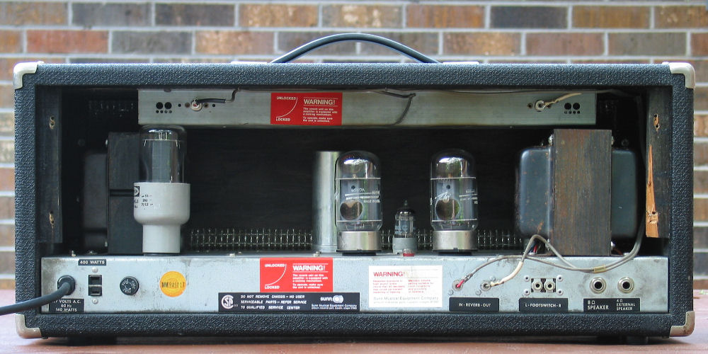
The Sunn uses a transformer driven tank so the left end of the tank (input) is either 4Ω or 8Ω. The right end (output) is about 2.5K. The connector is actually farther from the OT than the pic suggests. It's a Gibbs tank, all very similar to a Fender Accutronics tank. Neither jack is isolated from tank chassis. No hum issues with the Sunn circuit. I'm not recommending someone to mount a tank like this, just wanted to show that it can be done.
Interesting info Sluckey and Beasleybodyshop. May I point to the elephant in the room, so to speak. Both the Sunn and Showman reverb have the pt oriented differently from the tank. Both amps de facto have the tank rotated 90 degrees around the horizontal axis. It is the solution you know will work, because you've already tested it. So, what's holding you back? Sorry if I'm being a bit pushy. I'd like to solve it with the transformer in it's current position, but this hum problem seems to be a rather common 'design flaw' caused by either tank proximity or orientation to the pt.
The issue for me is that even with the pan rotated at 90degrees (horizontally) I had noise. I took a picture which is on the previous page with the test to make it easier to visualise. I tried each sides of the pan under the PT and then each side of the pan on the opposite side. All 4 trials had noise, and even more than the current “normal” set up.
So I don’t think rotating the PT 90 degrees (horizontally) will work. It would probably if I rotated it vertically.
The noise only goes away if I make my pan vertical (in place of the grill) like the Showman amp
That last sentence is exactly what I mean. So I do not mean the equivalent of sticking the pan out on the front or the back, like you tested. I mean the equivalent of mounting the pan against the front panel. Now you don't have room for that, but you might have enough room to rotate the pt to upright position, just like the Sunn. It will cost you a small aluminium plate to cover the hole in the chassis plus two end bells and a good amount of work. But it will probably solve all your reverb hum problems. To test this (probable) hypothesis you could follow my earlier suggestion to test this. Chassis on a desk, pt unmounted, cable ties clipped (if you're lucky it isn't more work than that), etc, etc.
I'm still hoping that there is a solution that is a lot easier, or better said that someone more knowledgable steps in and comes up with a better idea.
This is the best I managed so far.
1) removed pan of sleeve so I could move it as far from the PT as possible
2) used the ruby tubes pan with the extra shield underneath on the return
3) added a ceramic .01uF across the return
4) added a 220k/2200pF between the rca return and the tube grid
The audio is at at max, reverb at max and towards the end I reduce it to zero
With Master and reverb return at 1 o’clock it is not too bad, but not perfect
You do not have the required permissions to view the files attached to this post.
Bombacaototal wrote: ↑Sat Jan 18, 2020 5:35 pm
4) added a 220k/2200pF between the rca return and the tube grid
Is the 2200pF in series with the signal line or from signal line to gnd?
Did it reduce hum by a reasonable amount?
It’s from signal to ground. Didn’t make much difference to be honest, the .01uF across the pot must have taken care of the same frequency, but I prefer the sound of the reverb like this. It tightens the bottom end of the reverb.
If you want to wire it as a high pass filter you need to put it series with the signal.
i.e. output of the pan - 2200p cap in series - 220k to gnd - grid ( or grid stopper resistor if there is one).
If you put it from signal to gnd it will act as a low pass filter.
Since the output impedance of the reverb pan is pretty low it most likely won't have a noticeably effect on the 50 Hz (or is it 60 Hz) hum.
Correct me if I'm wrong, but won't a 2200pF cap from signal out of the pan to ground just bleed of highs? How much will depend of the output impedance of the pan of course, which is not the same for every pan. A high pass filter on the other hand might work to get rid of 60Hz. You could try a small cap in series before the 220k resistor to ground. Something like 1nF/1000pF. You could even come up with a very steep filter (24dB/oct) if you use inductors. Much like a high pass filter for a tweeter and thus cutting most of the 60Hz content.
Edit: I should read everything. So try what Marcus said, cheap and simple experiment that can be done with a few crocodile test leads
Is the 2200pF in series with the signal line or from signal line to gnd?
Did it reduce hum by a reasonable amount?
It’s from signal to ground. Didn’t make much difference to be honest, the .01uF across the pot must have taken care of the same frequency, but I prefer the sound of the reverb like this. It tightens the bottom end of the reverb.
If you want to wire it as a high pass filter you need to put it series with the signal.
i.e. output of the pan - 2200p cap in series - 220k to gnd - grid ( or grid stopper resistor if there is one).
If you put it from signal to gnd it will act as a low pass filter.
Since the output impedance of the reverb pan is pretty low it most likely won't have a noticeably effect on the 50 Hz (or is it 60 Hz) hum.
Thanks for clarifying Markus. It is interesting, but compared to only having the 220K to ground, having the 220k and 2200pF in parallel to ground made my reverb brighter and removed that “cave” low end echoness
Now the challenge of doing as suggested is that the rca jacks are really in the middle of the board, underneath. I think to attempt that I will need to remove the board and probably unsolder a bunch of stuff as leads are somewhat short. Not easy...sigh
You do not have the required permissions to view the files attached to this post.
Bombacaototal wrote: ↑Sat Jan 18, 2020 8:01 pm
Thanks for clarifying Markus. It is interesting, but compared to only having the 220K to ground, having the 220k and 2200pF in parallel to ground made my reverb brighter and removed that “cave” low end echoness
Now the challenge of doing as suggested is that the rca jacks are really in the middle of the board, underneath. I think to attempt that I will need to remove the board and probably unsolder a bunch of stuff as leads are somewhat short. Not easy...sigh
IIRC the 2n2 to gnd is supposed to make the frequency response of the reverb out flatter. i.e. it to some extent adds highs.
Don't recall why.
Currently you have a wire going from the RCA (pan out) jack to the grid of the recovery stage. Correct?
You just need to unsolder this wire at the grid and add the 1n or 2n2 cap in series.
Edit: Is the yellow wire connecting the RCA jack to the tube socket grid pin?
In case the 220k is directly soldered to the RCA jack you could just unsolder the yellow wire at the grid pin, insert the cap in series with the grid and add another 220k directly to gnd from the grid pin at the socket.
Edit 2:
Here is a link to some frequency response measurements glasman did with caps of different value added across the output coil.
However, In this case the cap is added directly from pan output to gnd, not via a 220k. https://ampgarage.com/forum/viewtopic.p ... nse#p64465
Help me out here, why not a cap in series right after the coil? Will that mess up the loading of the pan and thus the frequency response?
Edit. Interesting post about the cap to ground! Not what I expected, but not too surprising given the output is also a coil. Certainly something I'm going to try out.