I realize that changing the lower limit with VVR (cathode bias) is accomplished by changing the value of the resistor that ground references the pot. That said, is it just as simple as inserting a resistor between the pot and B+ in order to limit the upper limit? I have thought of doing this for a while, just don't recall seeing it anywhere. I'm wondering if there isn't another resistor between the MOSFET and B+.
Setting Voltage Limits With VVR
Moderators: pompeiisneaks, Colossal
-
dorrisant

- Posts: 2628
- Joined: Tue Sep 21, 2010 1:27 pm
- Location: Somewhere between a river and a cornfield
- Contact:
Setting Voltage Limits With VVR
You do not have the required permissions to view the files attached to this post.
"Education is what you're left with after you have forgotten what you have learned" - Enzo
Re: Setting Voltage Limits With VVR
Yes.is it just as simple as inserting a resistor between the pot and B+ in order to limit the upper limit?
Re: Setting Voltage Limits With VVR
I've done it in the amps i've built with 6AQ5 output tubes
dave
dave
-
dorrisant
- Posts: 2628
- Joined: Tue Sep 21, 2010 1:27 pm
- Location: Somewhere between a river and a cornfield
- Contact:
Re: Setting Voltage Limits With VVR
Sweet! Thanks for the replies.
"Education is what you're left with after you have forgotten what you have learned" - Enzo
Re: Setting Voltage Limits With VVR
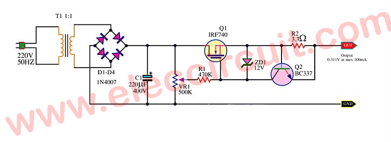
Even less widely known is that you can add a bipolar transistor and a couple of other parts and make that circuit also have a current limit.
This can be useful when you want to reduce current surges into a filter cap at power on or when changing off standby.
This can be useful when you want to reduce current surges into a filter cap at power on or when changing off standby.

Re: Setting Voltage Limits With VVR
Doesn't the 10R resistor in conjunction with the 12V zener already constitute a current limiting scheme?
Re: Setting Voltage Limits With VVR
Yep, that's the general idea.
Ten Over wrote: ↑Sun Feb 26, 2017 12:16 amIt does. It's a little sloppy, and depends on the threshold voltage and transconductance of the MOSFET. But it does limit and can be made to work.
The advantage of using a separate device like a bipolar is that the bipolar's threshold is both much smaller and more definite than the MOSFET's Vt. You get to use a much smaller sensing resistor, as it only has to generate 0.6V or so at the cutoff current, instead of the difference between the 12V zener and the Vt of the MOSFET. That's likely to be about 6-8V. A 10 ohm resistor will give a cutoff of about 700ma and dissipate 4.9W when that happens. A bipolar sense resistor would need to generate about 0.6V at that same 700ma, and dissipate 0.42W.
Re: Setting Voltage Limits With VVR
London Power's Power Scaling circuit as shown in TUT5 uses that set-up. O'Connor had also posted the circuit at 18watt many, many years ago.
dave
Re: Setting Voltage Limits With VVR
Yep, it's old. There was a version that used a bipolar pass device instead of a MOSFET in an old ARRK handbook I saw once. The MOSFET makes it easy to extend to high voltages and low drive currents.