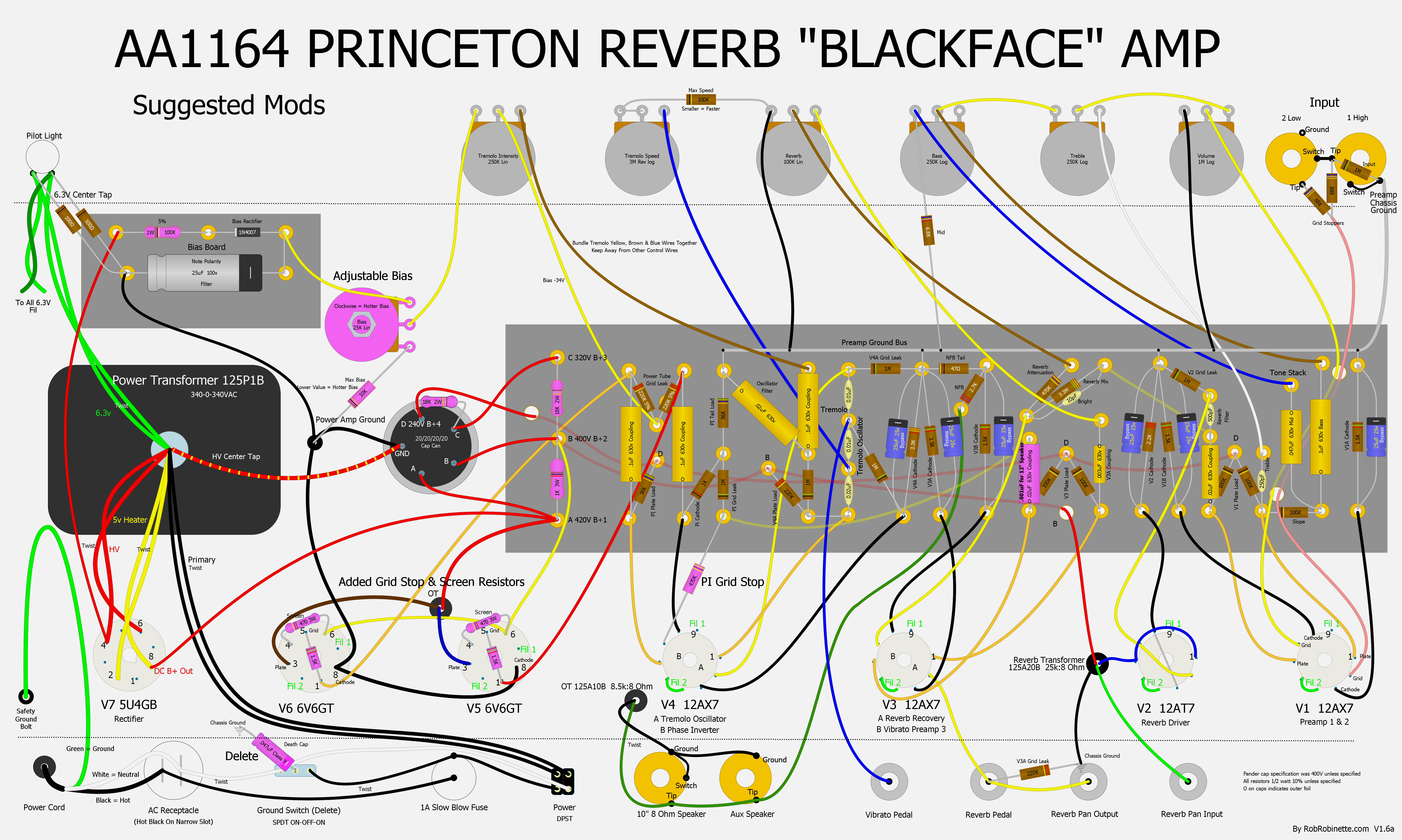
Yes, it depends which end the wire connects. In your most recent pic, it looks like you have your wire going straight to the grid and not through the grid stoppers first. Connect your wires at pin 1 so the signal passes through the 1.5K resistors.peckjed wrote: ↑Wed Oct 07, 2020 1:30 pmI added the 470K to the PI which made a nice difference. I also added the 1.5K and 470ohm screen resistor and grid stoppers to the 6v6's. Based on Robs layout (https://robrobinette.com/images/Guitar/ ... t_Mods.png) does it matter which end the wire connects to the grid on pin 1 or 5?Colossal wrote: ↑Mon Oct 05, 2020 3:35 pmThe grid stopper drops voltage and keeps the cathodyne from getting hit so hard and folding like cheap lawn furniture, producing the horrible frequency doubling effect and nasty distortion. Bigger values will smooth that out without killing any tone. You might try a 1M pot there and dial it in to your taste and then replace the pot with a fixed resistor.
Princeton Reverb build
Moderators: pompeiisneaks, Colossal
Re: Princeton Reverb build

Re: Princeton Reverb build
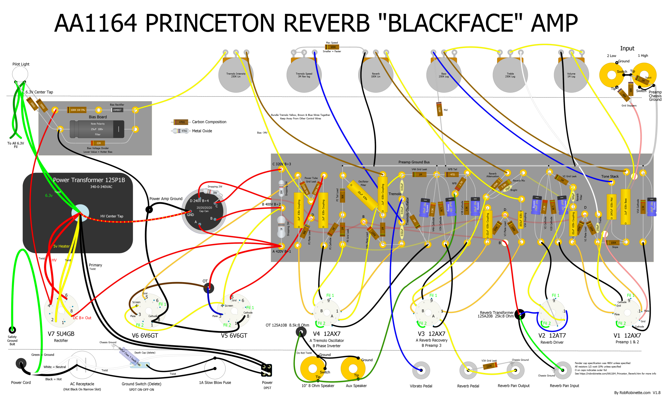
Correct. Pins 1 and 6 are unused in a 6V6 tube. The stock layout shows the power tube grid wires coming off of pin 5. If soldering the power tube grid stopper resistors between pins 5 and 1, connect the power tube grid wires to pin #1. Check RobRob's "stock" layout here. Note that Robinette connected pins 1 and 8 in the stock layout to, I believe, allow for use of EL34 tubes:rdavy wrote: ↑Sat Oct 10, 2020 12:46 pmYes, it depends which end the wire connects. In your most recent pic, it looks like you have your wire going straight to the grid and not through the grid stoppers first. Connect your wires at pin 1 so the signal passes through the 1.5K resistors.peckjed wrote: ↑Wed Oct 07, 2020 1:30 pmI added the 470K to the PI which made a nice difference. I also added the 1.5K and 470ohm screen resistor and grid stoppers to the 6v6's. Based on Robs layout (https://robrobinette.com/images/Guitar/ ... t_Mods.png) does it matter which end the wire connects to the grid on pin 1 or 5?Colossal wrote: ↑Mon Oct 05, 2020 3:35 pm
The grid stopper drops voltage and keeps the cathodyne from getting hit so hard and folding like cheap lawn furniture, producing the horrible frequency doubling effect and nasty distortion. Bigger values will smooth that out without killing any tone. You might try a 1M pot there and dial it in to your taste and then replace the pot with a fixed resistor.
And the modded one here. Note also that the modded power tube screens are rewired with resistors between pin 4 to pin 6, the leads coming off of pin 6.

Just plug it in, man.
Re: Princeton Reverb build
Thank you! I made those updates this morning.rdavy wrote: ↑Sat Oct 10, 2020 12:46 pmYes, it depends which end the wire connects. In your most recent pic, it looks like you have your wire going straight to the grid and not through the grid stoppers first. Connect your wires at pin 1 so the signal passes through the 1.5K resistors.peckjed wrote: ↑Wed Oct 07, 2020 1:30 pmI added the 470K to the PI which made a nice difference. I also added the 1.5K and 470ohm screen resistor and grid stoppers to the 6v6's. Based on Robs layout (https://robrobinette.com/images/Guitar/ ... t_Mods.png) does it matter which end the wire connects to the grid on pin 1 or 5?Colossal wrote: ↑Mon Oct 05, 2020 3:35 pm
The grid stopper drops voltage and keeps the cathodyne from getting hit so hard and folding like cheap lawn furniture, producing the horrible frequency doubling effect and nasty distortion. Bigger values will smooth that out without killing any tone. You might try a 1M pot there and dial it in to your taste and then replace the pot with a fixed resistor.