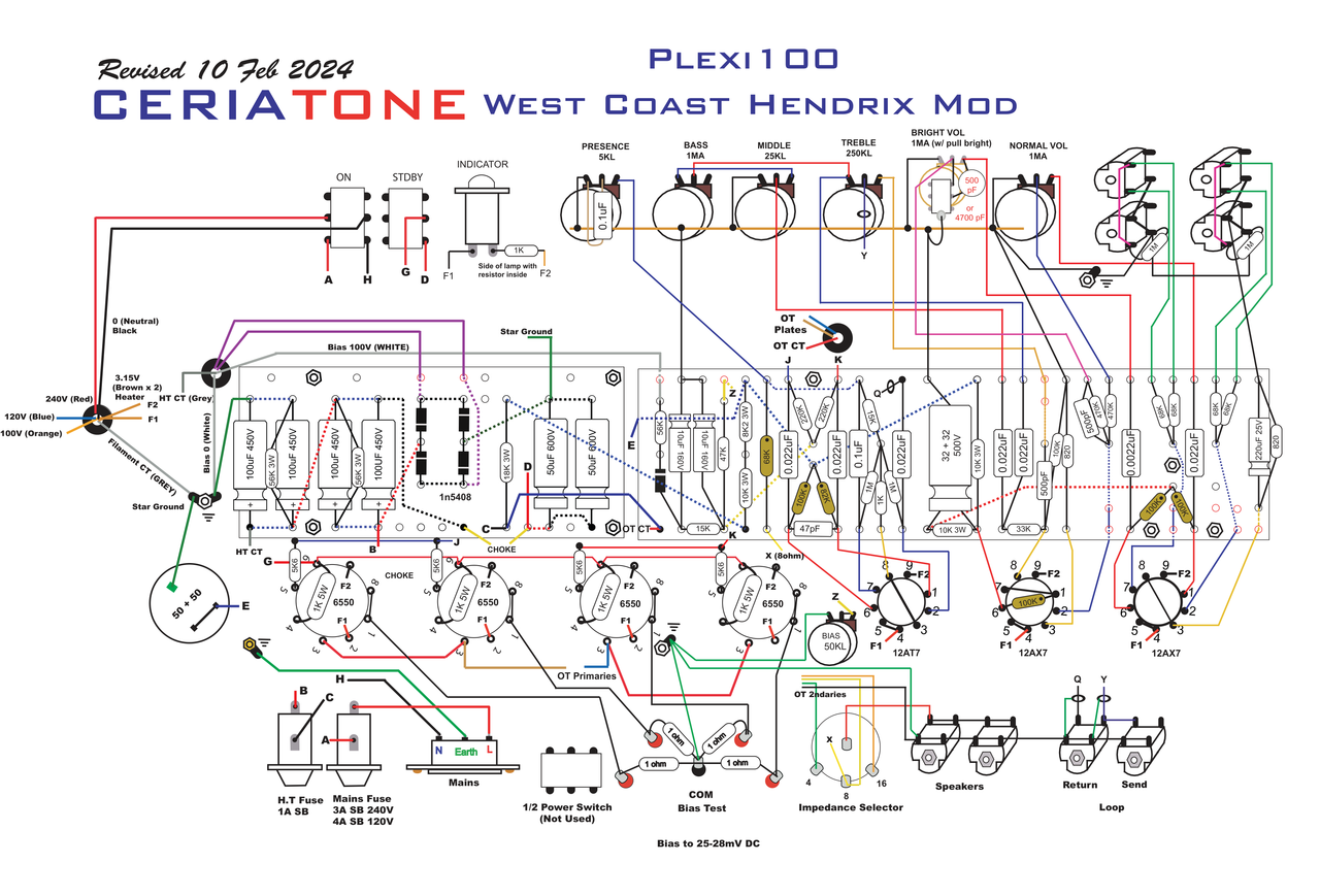
The amp that was the original inspiration for the B+/2 screen supply was the Ceriatone JTM100 JH West Coast mod. There they switch the screens ON with the SB. But in another thread someone pointed out that V2 would have high voltage on it in SB and stress V2.
So I'm trying to avoid that issue. I do have a DPDT SB switch.
Early brewers were primarily women, mostly because it was deemed a woman's job. Mesopotamian men, of some 3,800 years ago, were obviously complete assclowns and had yet to realize the pleasure of brewing beer.
It just occurred to me that taking the screen voltage from the point between the stacked reservoir caps won't work.
The caps alone can't supply any DC current.
Assuming 56k balancing resistors, even a screen current of 5mA would drop the voltage by 140V, as the source resistance at that point would be 28k.
At full output total screen current will be much larger than 5mA.
Fischerman wrote: ↑Sun Jul 19, 2026 11:15 am
this high-voltage JTM100 amp I'm building will have the screen supply taken from the middle of that main filter stack (i.e. - B+/2).
are you planning 560v on the plates and 280v on the screens? You may need 300v on the screens for full effect but 280v may be close enough.
The .047uf works ok here but is hardly necessary. But the screen supply won't work (w/o PT CT like you see on later Marshalls) since the current draw of the screens will pull down the voltage considerably despite the 56ks.
Fischerman wrote: ↑Mon Jul 20, 2026 12:18 am
The amp that was the original inspiration for the B+/2 screen supply was the Ceriatone JTM100 JH West Coast mod. There they switch the screens ON with the SB. But in another thread someone pointed out that V2 would have high voltage on it in SB and stress V2.
So I'm trying to avoid that issue. I do have a DPDT SB switch.
yes but this requires an PT with CT and a FULL WAVE BRIDGE Capacitor Input Load
Helmholtz wrote: ↑Fri Aug 07, 2026 12:48 am
It just occurred to me that taking the screen voltage from the point between the stacked reservoir caps won't work.
The caps alone can't supply any DC current.
Legit question...what do you think is the current source in an amplifier?
flemingmras wrote: ↑Fri Aug 07, 2026 2:06 pm
Legit question...what do you think is the current source in an amplifier?
In circuit analysis a circuit part that delivers a current is called a current source.
Other circuit parts connected to the output port of the source constitute the corresponding load.
Helmholtz wrote: ↑Fri Aug 07, 2026 3:45 pm
In circuit analysis a circuit part that delivers a current is called a current source.
Other circuit parts connected to the output port of the source constitute the corresponding load.
I was looking for a more specific answer based on a statement you made.
Helmholtz wrote:
The caps alone can't supply any DC current.
They absolutely can, and do! The amp is actually drawing from the filter capacitors. The power transformer continuously replenishes the charge as the amp draws from the capacitors.
Now...I would put a choke and a 2nd filter stage proceeding the FWB doubler center tap. But you can absolutely do it the way you were wanting to do it.
A single EL34 draws about 20mA screen current at full power out. At 400V, that's right at the 8 Watt screen dissipation limit. If you're doing a 4 tube amp, that'll be a max load of 40mA at that node.
Fischerman wrote: ↑Mon Jul 20, 2026 12:18 am
The amp that was the original inspiration for the B+/2 screen supply was the Ceriatone JTM100 JH West Coast mod. There they switch the screens ON with the SB. But in another thread someone pointed out that V2 would have high voltage on it in SB and stress V2.
So I'm trying to avoid that issue. I do have a DPDT SB switch.
yes but this requires an PT with CT and a FULL WAVE BRIDGE Capacitor Input Load
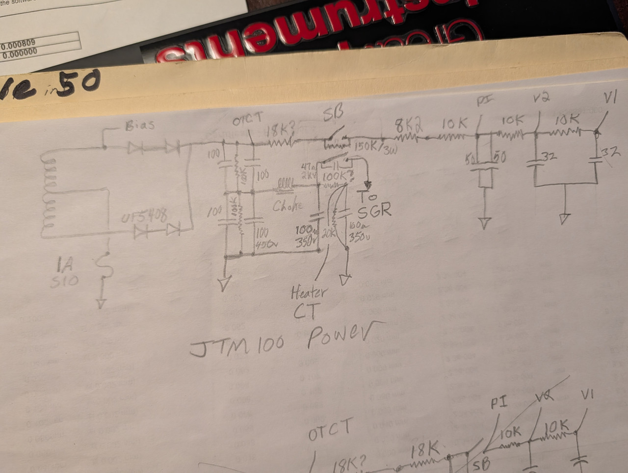
So this would not work? Sorry for sloppy labeling/etc.
Early brewers were primarily women, mostly because it was deemed a woman's job. Mesopotamian men, of some 3,800 years ago, were obviously complete assclowns and had yet to realize the pleasure of brewing beer.
Fischerman wrote: ↑Fri Aug 07, 2026 9:57 pm
So this would not work?
As said, that won't work.
The screen current will significantly pull down the voltage across the lower cap (while the voltage across the upper cap will increase by the same amount, likely exceeding its rated voltage).
It's way different from a FWB circuit with the CT connected between the caps.
Fischerman wrote: ↑Fri Aug 07, 2026 9:57 pm
So this would not work?
As said, that won't work.
The screen current will significantly pull down the voltage across the lower cap (while the voltage across the upper cap will increase by the same amount, likely exceeding its rated voltage).
It's way different from a FWB circuit with the CT connected between the caps.
Thanks! I was originally going to just add an extra 'node' in the power supply for lower screen voltage but was advised against that earlier itt. But that advice was probably in the context of a FW Bridge rectifier.
I'm really just trying to make a high voltage (560-ish vdc) JTM100 with 6550s that won't blow up or eat tubes. The transformers are built. The extra node seems like the easiest path now.
Early brewers were primarily women, mostly because it was deemed a woman's job. Mesopotamian men, of some 3,800 years ago, were obviously complete assclowns and had yet to realize the pleasure of brewing beer.