DIfferent assembly- look at the orientation of the markings on the electrolytics. Didn't you remake the boards at one point?
It's looking good though!
New HRM build
Moderators: pompeiisneaks, Colossal
-
martin manning

- Posts: 14058
- Joined: Sun Jul 06, 2008 12:43 am
- Location: 39°06' N 84°30' W
Re: New HRM build
Yes good pickup, the 12V board has a wire but the bias/rectifier board does not have a wire in that picture. I guess I forgot to put on the wire.martin manning wrote:DIfferent assembly- look at the orientation of the markings on the electrolytics. Didn't you remake the boards at one point?
It's looking good though!
BTW: I just got done jamming with the amp. The clean channel is fantastic, the OD needs some work, but I was expecting that. At least it did not blow up!
BTW: if you wondered what an amp sounds like with no ground on the bias circuit, it sounds like it is under water.
Last edited by ic-racer on Wed Dec 11, 2013 3:16 am, edited 1 time in total.
Re: New HRM build
OD "Needs some work" I'll say. I checked V2B and the voltage is in the 50 range. I tracked it down to a short on the HRM board. From the top I measure no resistance across the legs of one of the capacitors. So, either a solder bridge or a bad capacitor. Soldering iron is heating up now....
Re: New HRM build
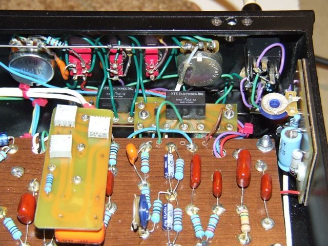
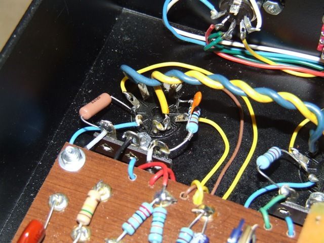
Something crazy going on around in the area of the HRM board; I'm losing my V2B plate voltage. Can't see anything from here, so the board has to come off.
[IMG:640:480]http://img.photobucket.com/albums/v670/ ... Mboard.jpg[/img]
Please ignore the two stacked series resisters in the lower right. I forgot to order a 24k (20k & 3k9 in there for now)
[IMG:640:480]http://img.photobucket.com/albums/v670/ ... Mboard.jpg[/img]
Please ignore the two stacked series resisters in the lower right. I forgot to order a 24k (20k & 3k9 in there for now)
Re: New HRM build
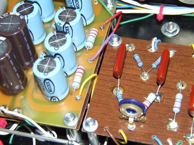
Get a look at this. There was a hairline copper trace, left over from the original outline of the component on the graphics program.
I scraped that off easily and now all is good! (This was one of the boards I had to re-do and make longer once I got my chassis).
[IMG:546:383]http://img.photobucket.com/albums/v670/ ... copper.jpg[/img]
I scraped that off easily and now all is good! (This was one of the boards I had to re-do and make longer once I got my chassis).
[IMG:546:383]http://img.photobucket.com/albums/v670/ ... copper.jpg[/img]
Last edited by ic-racer on Sun Oct 07, 2012 2:48 am, edited 2 times in total.
Re: New HRM build
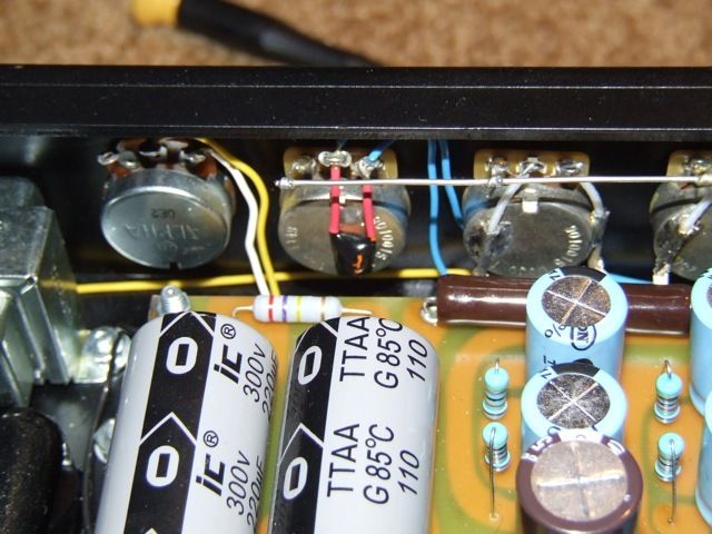
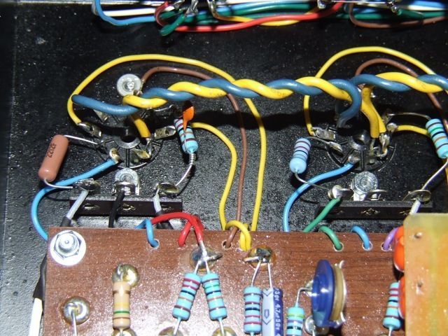
Setting the bias. I had too much bias voltage, even with the pot all the way off, so I replaced the 27k resistor at the base of the bias pot with a 22k.
I think that may be an error in the schematic, it should probably be 22k for EL34s.
[IMG:640:480]http://img.photobucket.com/albums/v670/ ... Jtubes.jpg[/img]
[IMG:640:480]http://img.photobucket.com/albums/v670/ ... ngbias.jpg[/img]
I think that may be an error in the schematic, it should probably be 22k for EL34s.
[IMG:640:480]http://img.photobucket.com/albums/v670/ ... Jtubes.jpg[/img]
[IMG:640:480]http://img.photobucket.com/albums/v670/ ... ngbias.jpg[/img]
Re: New HRM build
Wow, the clean channel is the best on any amp I have ever played! I got something right. In this amp I can actually hear the difference with the PI trim pot. The clean sound really got bigger and more open when it was set right. On my other amp I could not hear the difference.
I don't have enough time tonight to go through every permutation of the volume, drive, OD input trimmer and the 3 HRM trimmers.
One nice thing is that just about all the HRM trimmer settings sound good. Like different flavors of candy. Rather than a situation where one needs to find some single perfect setting that sounds good.
-
tubedogsmith
- Posts: 597
- Joined: Mon Jan 17, 2005 11:52 pm
Re: New HRM build
Looking good. It'd good,to see you posting again. The HRM has become my favorite circuit by far. Keep tweaking.
Re: New HRM build
Congrats on getting it done. 
I would love to try an HRM some day.
I would love to try an HRM some day.
Tom
Don't let that smoke out!
Don't let that smoke out!
-
dcribbs1412
- Posts: 1385
- Joined: Wed Jun 11, 2008 6:56 pm
- Location: Arizona Desert
Re: New HRM build
Congrats on a great looking build ic-racer
Darin
Darin
Re: New HRM build
Now that the dust has settled and the soldering smoke has cleared I wanted to summarize some things.
Build errors (listed here for my own note-keeping purposes. All have been easily corrected):
1) Forgot the small jumper between the top and middle prongs of the Mid Boost switch (symptom = no sound when mid boost is on).
2) Forgot to ground the bias power supply. Symptoms= could not bias tubes. They ran at 150ma. Briefly, of course, just long enough for me to see it on the meter and shut it down. DC voltage was in the -30sVDC. I could not find any reference to what it should be. By chance I checked for AC and it was 20VAC, this gave it away that it was not grounded. After the amp burns in a while and I'm happy with the sound I'll post a complete list of voltages, including Bias voltage (from what I recall it was around -55VDC).
3) Rogue copper on the HRM board from the fabrication process
4) I cut the cathode wire to V1 first stage too short This one has to loop up and around the tube socket. Only realizing it after mounting the main board with its backing board and soldering all the 30 or so other connections. Therefore no easy way to replace this wire. So , I swapped the location of cathode resistors compared to the V2 tube.
4) Probably schematic error. Bias pot resistor should probably be 22k, rather than 27k.
That is it! I'm a little amazed there were not more.
It also confirms that all the printed circuit patterns I drew (and previously posted) are functional. It did take quite a bit of thinking to get the relay boards and the FET board to both match the component and lead locations in the pictures, match the traces that show through the board and match the schematic! I hope others put those PC board patterns to good use.
Build errors (listed here for my own note-keeping purposes. All have been easily corrected):
1) Forgot the small jumper between the top and middle prongs of the Mid Boost switch (symptom = no sound when mid boost is on).
2) Forgot to ground the bias power supply. Symptoms= could not bias tubes. They ran at 150ma. Briefly, of course, just long enough for me to see it on the meter and shut it down. DC voltage was in the -30sVDC. I could not find any reference to what it should be. By chance I checked for AC and it was 20VAC, this gave it away that it was not grounded. After the amp burns in a while and I'm happy with the sound I'll post a complete list of voltages, including Bias voltage (from what I recall it was around -55VDC).
3) Rogue copper on the HRM board from the fabrication process
4) I cut the cathode wire to V1 first stage too short
4) Probably schematic error. Bias pot resistor should probably be 22k, rather than 27k.
That is it! I'm a little amazed there were not more.
It also confirms that all the printed circuit patterns I drew (and previously posted) are functional. It did take quite a bit of thinking to get the relay boards and the FET board to both match the component and lead locations in the pictures, match the traces that show through the board and match the schematic! I hope others put those PC board patterns to good use.
Re: New HRM build
Some pictures of the completed amp.
[IMG:640:480]http://img.photobucket.com/albums/v257/ ... CF5922.jpg[/img]
[IMG:640:480]http://img.photobucket.com/albums/v257/ ... CF5923.jpg[/img]
[IMG:640:480]http://img.photobucket.com/albums/v257/ ... CF5922.jpg[/img]
[IMG:640:480]http://img.photobucket.com/albums/v257/ ... CF5923.jpg[/img]
Re: New HRM build
[IMG:640:480]http://img.photobucket.com/albums/v257/ ... CF5924.jpg[/img]
[IMG:640:480]http://img.photobucket.com/albums/v257/ ... CF5927.jpg[/img]
[IMG:640:480]http://img.photobucket.com/albums/v257/ ... CF5927.jpg[/img]
Re: New HRM build
[IMG:640:480]http://img.photobucket.com/albums/v257/ ... CF5929.jpg[/img]
Re: New HRM build
[IMG:640:480]http://img.photobucket.com/albums/v257/ ... CF5930.jpg[/img]