I checked pot balance (ganging) by connecting both pots to a 9V battery and measuring output voltages at different settings.
When measuring signal difference in an amp using global NFB, results will likely look better because of NFB action.
Marshall JFM100 (Jimi's Favorite Marshall) build
Moderators: pompeiisneaks, Colossal
-
Fischerman
- Posts: 912
- Joined: Thu Dec 07, 2006 3:47 pm
- Location: Georgia
Re: Marshall JFM100 (Jimi's Favorite Marshall) build
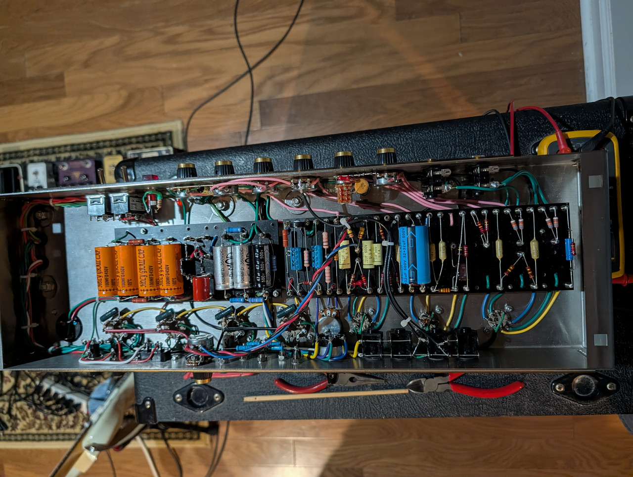
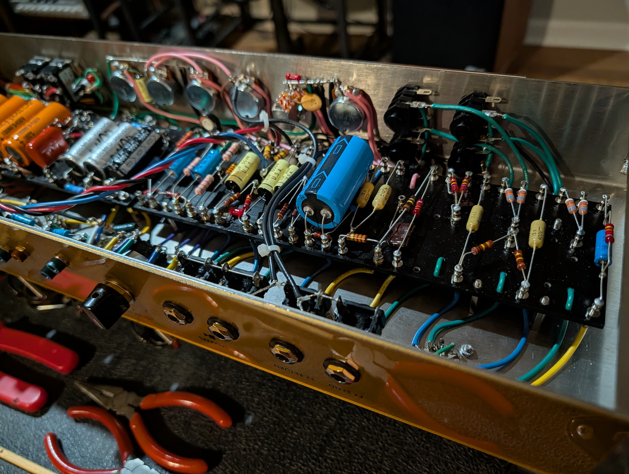
Initial build done but there is a hum. It goes away when I remove V2 but not when I remove V1. The amp makes what seems like normal sound and gets very loud and everything. Tone and Presence controls work fine. But hum is there when the MV is turned up (you can still barely hear it when MV is OFF). Turning up Bright volume makes it a little worse, turning up Normal volume has no effect.
Early brewers were primarily women, mostly because it was deemed a woman's job. Mesopotamian men, of some 3,800 years ago, were obviously complete assclowns and had yet to realize the pleasure of brewing beer.
-
Fischerman
- Posts: 912
- Joined: Thu Dec 07, 2006 3:47 pm
- Location: Georgia
Re: Marshall JFM100 (Jimi's Favorite Marshall) build
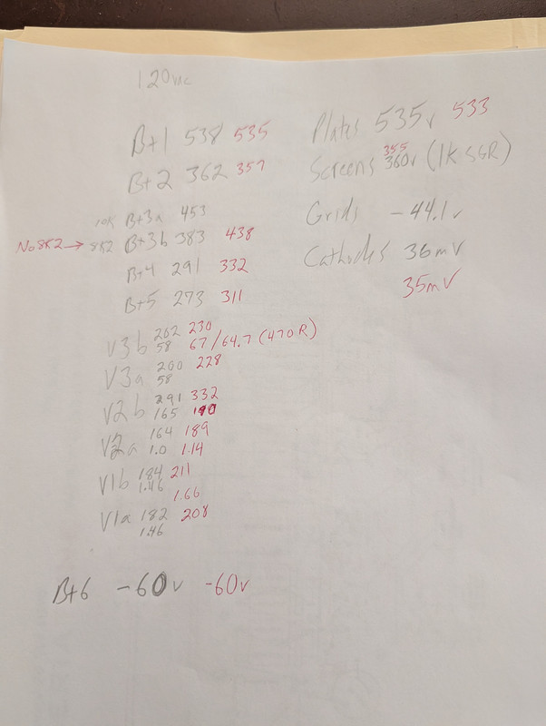
Voltages are lower than I wanted. It is exactly 560vdc unloaded with 120vac. I originally had 10k+8k2 droppers between B+ and PI node (written in pencil) then replaced the 8k2 with a jumper (red ink).
But the voltages look nominal to me. It has a 12AT7 in the PI.
The bass control has an effect on the hum volume. Turning it up increases hum.
EDIT: the good news is that it's been running on a 3A SLO Mains fuse because that's what came with the kit. Amazon just delivered some 4A SLO. I just took it for it's first tone test spin and when you turn it up even a little (it's a LOUD amp!) it's very powerful, punchy, and sounds really great. The volume control works great and is very useable, not hair trigger. Just need to sus out this hum. You don't really notice when it's at any volume but it's still way too much.
EDIT: At my 124vac wall voltage today it was idling at 558v, plates at 556v, cathodes at 30mV. The PI node is at 458v. So very close to target all around.
But the voltages look nominal to me. It has a 12AT7 in the PI.
The bass control has an effect on the hum volume. Turning it up increases hum.
EDIT: the good news is that it's been running on a 3A SLO Mains fuse because that's what came with the kit. Amazon just delivered some 4A SLO. I just took it for it's first tone test spin and when you turn it up even a little (it's a LOUD amp!) it's very powerful, punchy, and sounds really great. The volume control works great and is very useable, not hair trigger. Just need to sus out this hum. You don't really notice when it's at any volume but it's still way too much.
EDIT: At my 124vac wall voltage today it was idling at 558v, plates at 556v, cathodes at 30mV. The PI node is at 458v. So very close to target all around.
Early brewers were primarily women, mostly because it was deemed a woman's job. Mesopotamian men, of some 3,800 years ago, were obviously complete assclowns and had yet to realize the pleasure of brewing beer.
-
Fischerman
- Posts: 912
- Joined: Thu Dec 07, 2006 3:47 pm
- Location: Georgia
1 others liked this
Re: Marshall JFM100 (Jimi's Favorite Marshall) build
I finally hooked it up to a load box and really put it thru it's paces. I sort of expected the fully cranked tone to be a little farty in the bass but it's not, it's amazing jumpered with both volumes on 10 (MV on 10). Not nearly as crunchy/distorted as my EVH Superlead but just a killer cranked Hendrix tone with a Strat. The low notes have a nice 'kiss' to the front of the note but the note still has a powerful clarity to it. Even the neck pickup. Some (a lot) of that is probably due to the 12AT7 PI. The 18nF Mustards instead of 22nF probably didn't hurt. I still run the Bass on 2.
Regarding the hum, I think I've isolated it to the cathode(s) of V2. If I ground the grid of V2a the hum persists. If I pull V2 the hum goes away completely. I redid that ground and the hum improved but is still there. I originally had that ground and the dual preamp filter cap ground on a lug that was combined with (stacked on same bolt) the lug for the Mid/Presence ground buss. But those cathodes were noticeably more quiet when connected directly to the first ground buss (volumes, jacks, v1 cathode).
I think I might remove the bright switch. I've always been a fan of that big ass bright cap in a post-'68 Superlead but it's not right in this amp. That little 47pF dogbone is perfect. Then I might just run a ground buss all the way across the pots and see if that is more quiet. That V2 area is always a 'hot' area for noise.
So, for the record, here's where everything grounds:
IEC to a bolt near back corner between V7 and cap can
Power tube cathodes thru 1 ohm resistors to a bolt between V4/V5
OT secondary CT to speaker jacks, speaker jacks to same bolt as above
Main filter caps to a bolt near V7, near the corner of power board
PT secondary CT to same bolt as above (thru fuse)
Screen caps to a bolt under Presence (reminder: choke-input screen supply, if it matters here)
Bias to same bolt as above
Presence and Mid pots have a buss wire between them that is grounded to a bolt between Vol1/Treble
Volume pots have a buss wire between them that is grounded to a bolt between input jacks
Preamp dual filter grounded to buss above
V2 cathodes grounded to buss above
Input jacks grounded to buss above
Heater CT node from power board grounded to buss above
V1 cathodes connected to Channel two input jack ground
Regarding the hum, I think I've isolated it to the cathode(s) of V2. If I ground the grid of V2a the hum persists. If I pull V2 the hum goes away completely. I redid that ground and the hum improved but is still there. I originally had that ground and the dual preamp filter cap ground on a lug that was combined with (stacked on same bolt) the lug for the Mid/Presence ground buss. But those cathodes were noticeably more quiet when connected directly to the first ground buss (volumes, jacks, v1 cathode).
I think I might remove the bright switch. I've always been a fan of that big ass bright cap in a post-'68 Superlead but it's not right in this amp. That little 47pF dogbone is perfect. Then I might just run a ground buss all the way across the pots and see if that is more quiet. That V2 area is always a 'hot' area for noise.
So, for the record, here's where everything grounds:
IEC to a bolt near back corner between V7 and cap can
Power tube cathodes thru 1 ohm resistors to a bolt between V4/V5
OT secondary CT to speaker jacks, speaker jacks to same bolt as above
Main filter caps to a bolt near V7, near the corner of power board
PT secondary CT to same bolt as above (thru fuse)
Screen caps to a bolt under Presence (reminder: choke-input screen supply, if it matters here)
Bias to same bolt as above
Presence and Mid pots have a buss wire between them that is grounded to a bolt between Vol1/Treble
Volume pots have a buss wire between them that is grounded to a bolt between input jacks
Preamp dual filter grounded to buss above
V2 cathodes grounded to buss above
Input jacks grounded to buss above
Heater CT node from power board grounded to buss above
V1 cathodes connected to Channel two input jack ground
Early brewers were primarily women, mostly because it was deemed a woman's job. Mesopotamian men, of some 3,800 years ago, were obviously complete assclowns and had yet to realize the pleasure of brewing beer.
Re: Marshall JFM100 (Jimi's Favorite Marshall) build
voltages on v1 seem low. try to increase preamp voltages a bitFischerman wrote: ↑Sat Sep 19, 2026 9:21 pm Voltages are lower than I wanted. It is exactly 560vdc unloaded with 120vac. I originally had 10k+8k2 droppers between B+ and PI node (written in pencil) then replaced the 8k2 with a jumper (red ink).
But the voltages look nominal to me. It has a 12AT7 in the PI.
The bass control has an effect on the hum volume. Turning it up increases hum.
EDIT: the good news is that it's been running on a 3A SLO Mains fuse because that's what came with the kit. Amazon just delivered some 4A SLO. I just took it for it's first tone test spin and when you turn it up even a little (it's a LOUD amp!) it's very powerful, punchy, and sounds really great. The volume control works great and is very useable, not hair trigger. Just need to sus out this hum. You don't really notice when it's at any volume but it's still way too much.
EDIT: At my 124vac wall voltage today it was idling at 558v, plates at 556v, cathodes at 30mV. The PI node is at 458v. So very close to target all around.
Re: Marshall JFM100 (Jimi's Favorite Marshall) build
Try mains filter cap directly to PT CT (without anything else added here). then connect main filter cap to groundFischerman wrote: ↑Mon Sep 21, 2026 12:30 pm Main filter caps to a bolt near V7, near the corner of power board
PT secondary CT to same bolt as above (thru fuse)
-
Fischerman
- Posts: 912
- Joined: Thu Dec 07, 2006 3:47 pm
- Location: Georgia
Re: Marshall JFM100 (Jimi's Favorite Marshall) build
Thanks! So connect main filter cap ground to the fuseblock? Or fuseblock to main filter grounds on board? Either way it looks like you want them connected together, then one wire to ground lug. Is that right?Roe wrote: ↑Mon Sep 21, 2026 3:06 pmTry mains filter cap directly to PT CT (without anything else added here). then connect main filter cap to groundFischerman wrote: ↑Mon Sep 21, 2026 12:30 pm Main filter caps to a bolt near V7, near the corner of power board
PT secondary CT to same bolt as above (thru fuse)
Regarding the preamp voltages, at wall voltage I get 326v on that node and ~220v plates on V1. I think the 12AT7 in the PI draws more current so there is a bigger drop there than normal. That's my guess why it's a big drop there. Plus the original didn't even have the extra node there. V1 drew from same supply as V2 in the old 1959T schematic. I might experiment there but it's still honeymoon phase regarding the tone. It sounds really great.
Then I roll the volume off and remember, oh yeah, that hum.
Early brewers were primarily women, mostly because it was deemed a woman's job. Mesopotamian men, of some 3,800 years ago, were obviously complete assclowns and had yet to realize the pleasure of brewing beer.
Re: Marshall JFM100 (Jimi's Favorite Marshall) build
1 connect mains filter cap ground directly to CT w/o anything else connected to CT or to wire. This wire will be noisy.Fischerman wrote: ↑Mon Sep 21, 2026 3:37 pmThanks! So connect main filter cap ground to the fuseblock? Or fuseblock to main filter grounds on board? Either way it looks like you want them connected together, then one wire to ground lug. Is that right?Roe wrote: ↑Mon Sep 21, 2026 3:06 pmTry mains filter cap directly to PT CT (without anything else added here). then connect main filter cap to groundFischerman wrote: ↑Mon Sep 21, 2026 12:30 pm Main filter caps to a bolt near V7, near the corner of power board
PT secondary CT to same bolt as above (thru fuse)
Regarding the preamp voltages, at wall voltage I get 326v on that node and ~220v plates on V1. I think the 12AT7 in the PI draws more current so there is a bigger drop there than normal. That's my guess why it's a big drop there. Plus the original didn't even have the extra node there. V1 drew from same supply as V2 in the old 1959T schematic. I might experiment there but it's still honeymoon phase regarding the tone. It sounds really great.
Then I roll the volume off and remember, oh yeah, that hum.
2 connect mains filter cap to ground
-
Fischerman
- Posts: 912
- Joined: Thu Dec 07, 2006 3:47 pm
- Location: Georgia
Re: Marshall JFM100 (Jimi's Favorite Marshall) build
I keep reading this thinking, 'how do I connect directly to CT when the CT is a red/yellow wire that comes out of transformer and is right now connected to the HT fuseblock'. In my mind, I'm connecting the CT to something. Maybe you're thinking it is a laydown PT with a CT lug? This PT is wired.Roe wrote: ↑Mon Sep 21, 2026 4:14 pm1 connect mains filter cap ground directly to CT w/o anything else connected to CT or to wire. This wire will be noisy.Fischerman wrote: ↑Mon Sep 21, 2026 3:37 pmThanks! So connect main filter cap ground to the fuseblock? Or fuseblock to main filter grounds on board? Either way it looks like you want them connected together, then one wire to ground lug. Is that right?
Regarding the preamp voltages, at wall voltage I get 326v on that node and ~220v plates on V1. I think the 12AT7 in the PI draws more current so there is a bigger drop there than normal. That's my guess why it's a big drop there. Plus the original didn't even have the extra node there. V1 drew from same supply as V2 in the old 1959T schematic. I might experiment there but it's still honeymoon phase regarding the tone. It sounds really great.
Then I roll the volume off and remember, oh yeah, that hum.
2 connect mains filter cap to ground
If so then maybe I should go red/yellow wire (CT) to main filter cap grounds on power board. Then power board ground wire to fuseblock, then FB to ground.
Early brewers were primarily women, mostly because it was deemed a woman's job. Mesopotamian men, of some 3,800 years ago, were obviously complete assclowns and had yet to realize the pleasure of brewing beer.
Re: Marshall JFM100 (Jimi's Favorite Marshall) build
To minimise the interaction of ripple
current with the rest of the circuit, the
transformer-rectifier-reservoir must be
treated as a single, selfcontained
circuit block.
In some schematics this
is emphasised by drawing
the circuit in a more
compact fashion, as in
fig. 15.5, and the circuit
should be physically built
in a similarly compact
way.* The rest of the
amplifier will then be
connected directly to the
terminals of the reservoir capacitor. Connections to any other points on this noisy
current loop are not allowed, and no part of this network may be connected to the
chassis if a quiet ground scheme is to be maintained! Some very sensitive
preamplifiers may even shield this part of the power supply from the audio circuit
with a metal bulkhead or screening can. (p. 266)
current with the rest of the circuit, the
transformer-rectifier-reservoir must be
treated as a single, selfcontained
circuit block.
In some schematics this
is emphasised by drawing
the circuit in a more
compact fashion, as in
fig. 15.5, and the circuit
should be physically built
in a similarly compact
way.* The rest of the
amplifier will then be
connected directly to the
terminals of the reservoir capacitor. Connections to any other points on this noisy
current loop are not allowed, and no part of this network may be connected to the
chassis if a quiet ground scheme is to be maintained! Some very sensitive
preamplifiers may even shield this part of the power supply from the audio circuit
with a metal bulkhead or screening can. (p. 266)
You do not have the required permissions to view the files attached to this post.
-
Fischerman
- Posts: 912
- Joined: Thu Dec 07, 2006 3:47 pm
- Location: Georgia
Re: Marshall JFM100 (Jimi's Favorite Marshall) build
Thanks. It all seems to make sense until it says 'no part of this network may be connected to theRoe wrote: ↑Mon Sep 21, 2026 4:48 pm To minimise the interaction of ripple
current with the rest of the circuit, the
transformer-rectifier-reservoir must be
treated as a single, selfcontained
circuit block.
In some schematics this
is emphasised by drawing
the circuit in a more
compact fashion, as in
fig. 15.5, and the circuit
should be physically built
in a similarly compact
way.* The rest of the
amplifier will then be
connected directly to the
terminals of the reservoir capacitor. Connections to any other points on this noisy
current loop are not allowed, and no part of this network may be connected to the
chassis if a quiet ground scheme is to be maintained! Some very sensitive
preamplifiers may even shield this part of the power supply from the audio circuit
with a metal bulkhead or screening can. (p. 266)
chassis'. To me, it seems the electrons have to come from somewhere and they only can enter thru the power cable which is connected to the chassis. No connection to chassis, no electrons to flow. It's not 'grounded' unless is connects to 'ground' and there is only one way to 'ground'...thru the power cable and thus thru the chassis.
If I can't connect to chassis, what is this noisy loop connected to to be considered 'grounded'?
Early brewers were primarily women, mostly because it was deemed a woman's job. Mesopotamian men, of some 3,800 years ago, were obviously complete assclowns and had yet to realize the pleasure of brewing beer.
Re: Marshall JFM100 (Jimi's Favorite Marshall) build
Read more. The ground buss is connected to the chassis at v1 normally. and the IEC is also connected to chassisFischerman wrote: ↑Mon Sep 21, 2026 5:47 pmThanks. It all seems to make sense until it says 'no part of this network may be connected to theRoe wrote: ↑Mon Sep 21, 2026 4:48 pm To minimise the interaction of ripple
current with the rest of the circuit, the
transformer-rectifier-reservoir must be
treated as a single, selfcontained
circuit block.
In some schematics this
is emphasised by drawing
the circuit in a more
compact fashion, as in
fig. 15.5, and the circuit
should be physically built
in a similarly compact
way.* The rest of the
amplifier will then be
connected directly to the
terminals of the reservoir capacitor. Connections to any other points on this noisy
current loop are not allowed, and no part of this network may be connected to the
chassis if a quiet ground scheme is to be maintained! Some very sensitive
preamplifiers may even shield this part of the power supply from the audio circuit
with a metal bulkhead or screening can. (p. 266)
chassis'. To me, it seems the electrons have to come from somewhere and they only can enter thru the power cable which is connected to the chassis. No connection to chassis, no electrons to flow. It's not 'grounded' unless is connects to 'ground' and there is only one way to 'ground'...thru the power cable and thus thru the chassis.
If I can't connect to chassis, what is this noisy loop connected to to be considered 'grounded'?
Last edited by Roe on Tue Sep 22, 2026 7:32 am, edited 1 time in total.
Re: Marshall JFM100 (Jimi's Favorite Marshall) build
What power tubes are you running?Fischerman wrote: ↑Mon Sep 21, 2026 12:30 pm I finally hooked it up to a load box and really put it thru it's paces. I sort of expected the fully cranked tone to be a little farty in the bass but it's not, it's amazing jumpered with both volumes on 10 (MV on 10). Not nearly as crunchy/distorted as my EVH Superlead but just a killer cranked Hendrix tone with a Strat. The low notes have a nice 'kiss' to the front of the note but the note still has a powerful clarity to it. Even the neck pickup. Some (a lot) of that is probably due to the 12AT7 PI. The 18nF Mustards instead of 22nF probably didn't hurt. I still run the Bass on 2.
-
Fischerman
- Posts: 912
- Joined: Thu Dec 07, 2006 3:47 pm
- Location: Georgia
1 others liked this
Re: Marshall JFM100 (Jimi's Favorite Marshall) build
Sovtek 6550Roe wrote: ↑Tue Sep 22, 2026 7:29 amWhat power tubes are you running?Fischerman wrote: ↑Mon Sep 21, 2026 12:30 pm I finally hooked it up to a load box and really put it thru it's paces. I sort of expected the fully cranked tone to be a little farty in the bass but it's not, it's amazing jumpered with both volumes on 10 (MV on 10). Not nearly as crunchy/distorted as my EVH Superlead but just a killer cranked Hendrix tone with a Strat. The low notes have a nice 'kiss' to the front of the note but the note still has a powerful clarity to it. Even the neck pickup. Some (a lot) of that is probably due to the 12AT7 PI. The 18nF Mustards instead of 22nF probably didn't hurt. I still run the Bass on 2.
Regarding the grounds, I see that the ground buss is grounded at v1 and that the IEC is grounded. But to then have that 'noisy loop' not grounded is what sort of blows my mind. It can't be connected to the ground buss because that is connected to chassis and that violates the 'no part of this network may be connected to the
chassis' rule.
Early brewers were primarily women, mostly because it was deemed a woman's job. Mesopotamian men, of some 3,800 years ago, were obviously complete assclowns and had yet to realize the pleasure of brewing beer.
Re: Marshall JFM100 (Jimi's Favorite Marshall) build
It should be connected to chassis indirectly at v1 but not directly (at rectifier or mains cap). particularly grounding the rectifier directly to chassis risks noise.Fischerman wrote: ↑Tue Sep 22, 2026 10:30 amSovtek 6550Roe wrote: ↑Tue Sep 22, 2026 7:29 amWhat power tubes are you running?Fischerman wrote: ↑Mon Sep 21, 2026 12:30 pm I finally hooked it up to a load box and really put it thru it's paces. I sort of expected the fully cranked tone to be a little farty in the bass but it's not, it's amazing jumpered with both volumes on 10 (MV on 10). Not nearly as crunchy/distorted as my EVH Superlead but just a killer cranked Hendrix tone with a Strat. The low notes have a nice 'kiss' to the front of the note but the note still has a powerful clarity to it. Even the neck pickup. Some (a lot) of that is probably due to the 12AT7 PI. The 18nF Mustards instead of 22nF probably didn't hurt. I still run the Bass on 2.
Regarding the grounds, I see that the ground buss is grounded at v1 and that the IEC is grounded. But to then have that 'noisy loop' not grounded is what sort of blows my mind. It can't be connected to the ground buss because that is connected to chassis and that violates the 'no part of this network may be connected to the chassis' rule.