The original intent of the eyelet board drawings was to enable a DIY replacement for the PCB and Preamp board set, with the same overall dimensions and mounting centers. The preamp board layout closely matches Dumble's ODS component layout (post-2nd Gen), so any important interactions should be preserved. Notable differences are:
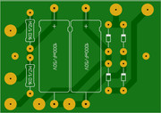
- All of the high voltage power supply filters are located on the main filter board, eliminating the need for the remotely-mounted B+4 and B+5 filter capacitors seen in some layouts.
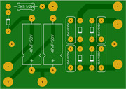
- The bias supply circuit has two filters, as seen in later SN amps. Refer to the #183 layout drawing for details of the B+ connections to the preamp board and the bias trimmer pot.
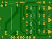
- The FET board layout required some rework for eyelet construction within the same dimensions as the PCB, but it has been proven to work well.
Also included here is an alternate bipolar power supply for the SSS driver tube.