An aluminum chassis is a perfect heatsink on its own.
Nevertheless I'd add thermal grease.
Biasing AC-30 amps?
Moderators: pompeiisneaks, Colossal
Re: Biasing AC-30 amps?
It will reduce the HT power supply voltage, and hence HT current, and from that, all other voltages related to HT current.
What was your reason for doing that?I put a 100 ohm resistor between the valve rectifier (5AR4) and the output stage of an 5F1 Champ clone
I suppose you preferred the sound of that amp with a higher voltage, hotter operating point.the amp didn’t sound so good when the amp distorted. I imagine it could be worse with an amp with greater wattage.
However I'm not sure that can then be extrapolated to all amps.
Or why it should be even more the case with higher power amps.
What's your thinking?
https://www.justgiving.com/page/5-in-5-for-charlie This is my step son and his family. He is running 5 marathons in 5 days to support the research into STXBP1, the genetic condition my grandson Charlie has. Please consider supporting him!
Re: Biasing AC-30 amps?
I found the rail voltage of the Champ increased as signal was applied to the amp and the volume turned up. However once the amp started to distort the rail voltage would sag.Littlewyan wrote: ↑Tue Jul 21, 2026 12:52 pm It recreates the sag of a valve rectifier. Some newer Voxes use it, like the AC15C1, instead of a valve rectifier. So it’ll give a softer response which may be desirable in your case as the original AC30s had valve rectifiers.
Not sure about the Champ as Class A doesn’t sag. If you’re worried about the effect you could start smaller, 47ohm total instead of 100Ohm.
Did you measure the screen current?
Yours Sincerely
Mark Abbott
Mark Abbott
Re: Biasing AC-30 amps?
The reason was to minimise the power supply hum in class A amps by making a pi filter. The amp was quieter with the extra filtering.I put a 100 ohm resistor between the valve rectifier (5AR4) and the output stage of an 5F1 Champ clone
What was your reason for doing that?
In the case of the Champ, the rail voltage increases as signal increases but this only occurs till the amp distorts, then the rail voltage decreases, and the 100 ohm resistor caused a further reduction in rail voltage which made the amp sound quite mid heavy and the amp wasn’t as loud.the amp didn’t sound so good when the amp distorted. I imagine it could be worse with an amp with greater wattage.
I suppose you preferred the sound of that amp with a higher voltage, hotter operating point.
However I'm not sure that can then be extrapolated to all amps.
Or why it should be even more the case with higher power amps.
What's your thinking?
Yours Sincerely
Mark Abbott
Mark Abbott
Re: Biasing AC-30 amps?
with a 50R cathode resistor, AC30s tend to draw 200ma at idle and 250ma at full power but this includes preamp (which may draw 10-12ma, depending on circuit and tubes)Littlewyan wrote: ↑Mon Jul 20, 2026 7:06 pm Ball park figure from the EL84 datasheet is 228mA total for 4 x EL84s (Screen and anode current max dissipation).
-
pdf64
- Posts: 3096
- Joined: Sat Mar 12, 2011 9:23 pm
- Location: Staffordshire, UK
- Contact:
1 others liked this
Re: Biasing AC-30 amps?
With cathode bias, every option to reduce idle dissipation will also reduce power output. Hence fixed bias became the norm for higher power amps.Mark wrote: ↑Wed Jul 22, 2026 8:06 am ... In the case of the Champ, the rail voltage increases as signal increases but this only occurs till the amp distorts, then the rail voltage decreases, and the 100 ohm resistor caused a further reduction in rail voltage which made the amp sound quite mid heavy and the amp wasn’t as loud.
And I'm not sure of the mechanism, but higher HT voltage often seems to result in a slightly brighter tone.
But I don't think the AC30 you have there will be lacking in brightness if the HT characteristics are altered to be more akin to a mid 60s model.
Last edited by pdf64 on Wed Jul 22, 2026 12:06 pm, edited 1 time in total.
https://www.justgiving.com/page/5-in-5-for-charlie This is my step son and his family. He is running 5 marathons in 5 days to support the research into STXBP1, the genetic condition my grandson Charlie has. Please consider supporting him!
-
pdf64
- Posts: 3096
- Joined: Sat Mar 12, 2011 9:23 pm
- Location: Staffordshire, UK
- Contact:
1 others liked this
Re: Biasing AC-30 amps?
As the HT voltage (and stiffness) on AC30 designs was increased through the 70s and 80s, current draw and hence idle dissipation inevitably increased too.Roe wrote: ↑Wed Jul 22, 2026 8:09 amwith a 50R cathode resistor, AC30s tend to draw 200ma at idle and 250ma at full power but this includes preamp (which may draw 10-12ma, depending on circuit and tubes)Littlewyan wrote: ↑Mon Jul 20, 2026 7:06 pm Ball park figure from the EL84 datasheet is 228mA total for 4 x EL84s (Screen and anode current max dissipation).
https://www.justgiving.com/page/5-in-5-for-charlie This is my step son and his family. He is running 5 marathons in 5 days to support the research into STXBP1, the genetic condition my grandson Charlie has. Please consider supporting him!
-
pdf64
- Posts: 3096
- Joined: Sat Mar 12, 2011 9:23 pm
- Location: Staffordshire, UK
- Contact:
1 others liked this
Re: Biasing AC-30 amps?
I think you might not be taking account of the high crest factor ripple currents required to charge the reservoir cap, which will significantly increase resistor dissipation.Littlewyan wrote: ↑Mon Jul 20, 2026 7:06 pm Depends on what's possible with the room you have or the layout.
AC side - Gives the diodes some protection if there's an inrush of current and you can split the resistance in half.
DC side - Only one resistor required but you'll need twice the wattage
... If we use resistors on the AC side we can get away with 2 x 47Ohm 5W resistors. If we go with the DC side we'll need a 15W 100Ohm resistor and unless we can panel mount it, we're getting big!
Also current on the AC side of the rectifier is higher than in the DC side, and in the 2 phase arrangement each leg carries 0.707 of the total.
And with the 2 phase, a single resistor can be used at low voltage on the CT return to 0V common.
But this amp probably uses a non tapped winding with FWB rectifier.
As I recall I used a chassis mounted 50W 100R in the AC side for the mid 80s AC30TBR, to get the 370V HT down to a more reasonable level. A 25W resistor got hotter than I was happy with.
https://www.justgiving.com/page/5-in-5-for-charlie This is my step son and his family. He is running 5 marathons in 5 days to support the research into STXBP1, the genetic condition my grandson Charlie has. Please consider supporting him!
Re: Biasing AC-30 amps?
I am not sure about this. The (collective) screen resistance was increased to 780R (instead of a choke with a 420r+ dc resistance). this may limit the current draw a bitpdf64 wrote: ↑Wed Jul 22, 2026 10:00 amAs the HT voltage (and stiffness) on AC30 designs was increased through the 70s and 80s, current draw and hence idle dissipation inevitably increased too.Roe wrote: ↑Wed Jul 22, 2026 8:09 amwith a 50R cathode resistor, AC30s tend to draw 200ma at idle and 250ma at full power but this includes preamp (which may draw 10-12ma, depending on circuit and tubes)Littlewyan wrote: ↑Mon Jul 20, 2026 7:06 pm Ball park figure from the EL84 datasheet is 228mA total for 4 x EL84s (Screen and anode current max dissipation).
Re: Biasing AC-30 amps?
What schematic version are you speaking of, as this one (file:///C:/Users/User/Downloads/70s%20AC30_TBR-2.pdf) shows a 20H choke and a 20R/13W B+ dropper?
-
sluckey
- Posts: 3864
- Joined: Sun Jul 22, 2007 7:48 pm
- Location: Mobile, AL
- Contact:
1 others liked this
Re: Biasing AC-30 amps?
Oh sorry, it's the pdf from the second post of this thread: https://ampgarage.com/forum/viewtopic.php?t=38103
Re: Biasing AC-30 amps?
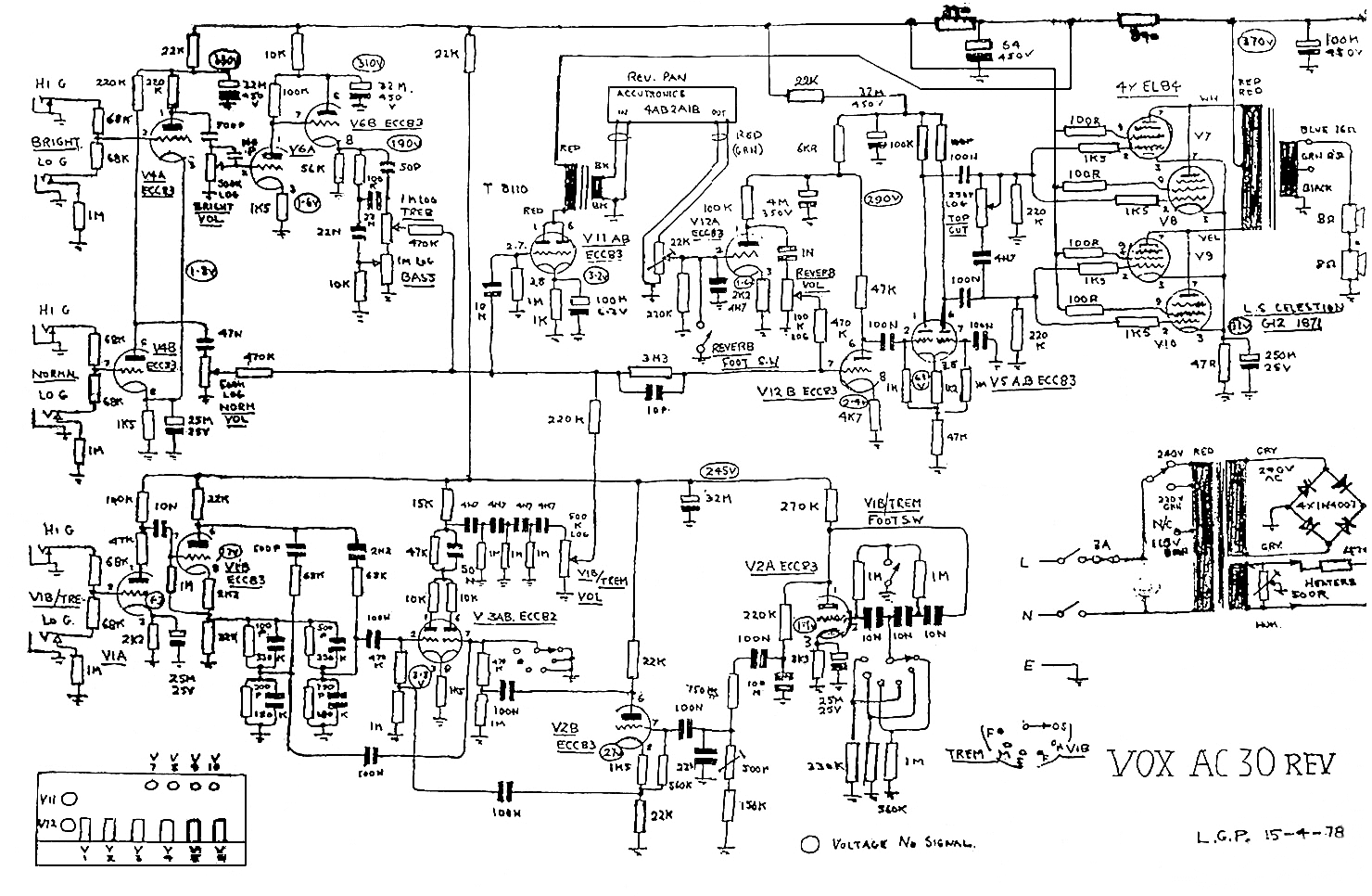
this is the 1978-79 rose morris variant with ss rectifier and no choke
https://www.drtube.com/schematics/vox/ac30-rev.gif
-
pdf64
- Posts: 3096
- Joined: Sat Mar 12, 2011 9:23 pm
- Location: Staffordshire, UK
- Contact:
2 others liked this
Re: Biasing AC-30 amps?
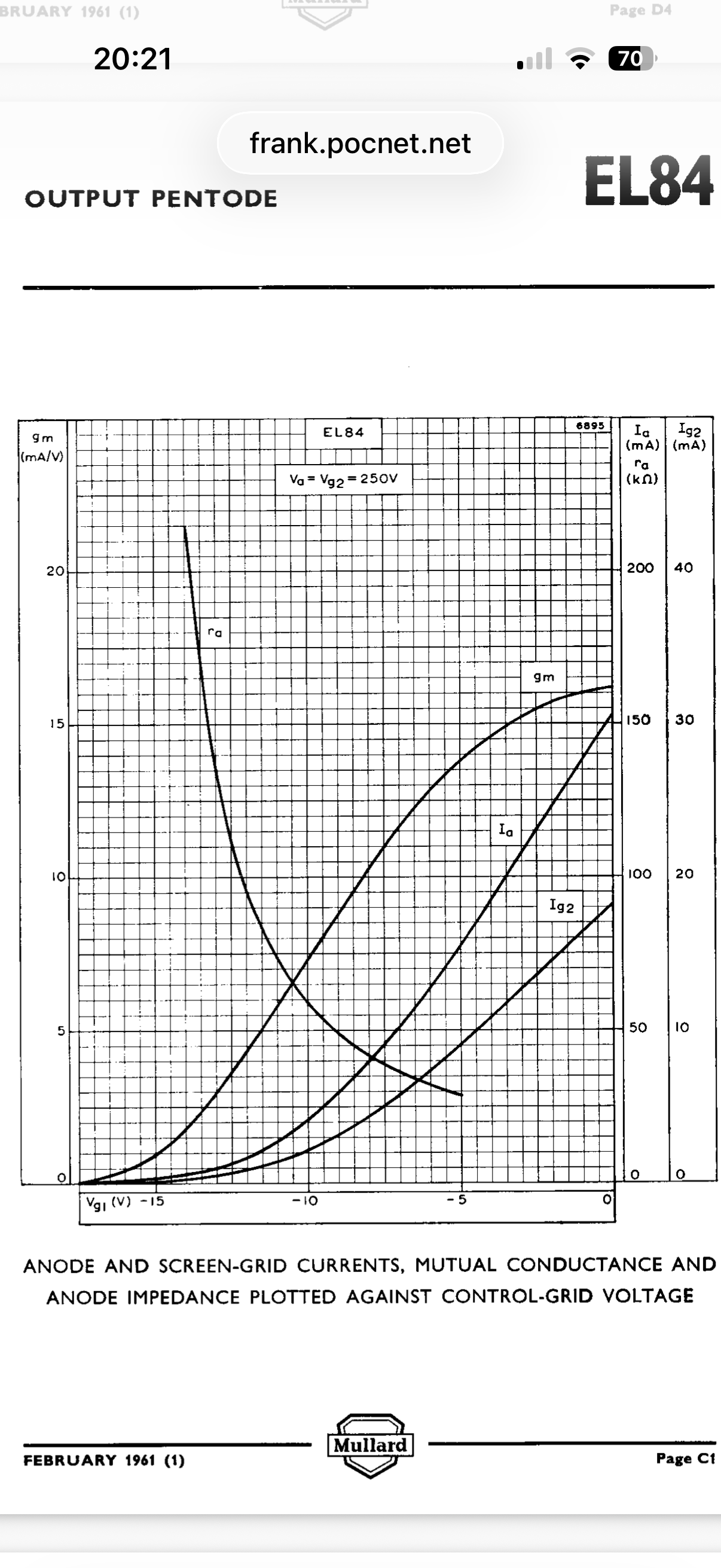
Yes, but it's more of a peak current than idling. Screen grids draw a lot more peak current, when the instantaneous Vg1-k=0, than when idling, even when it's a hot idle.Roe wrote: ↑Wed Jul 22, 2026 2:16 pmI am not sure about this. The (collective) screen resistance was increased to 780R (instead of a choke with a 420r+ dc resistance). this may limit the current draw a bit
This is the schematic with 780R resistance between OT CT and screen grid supply nodes
https://www.drtube.com/schematics/vox/ac30-rev.gif
https://www.justgiving.com/page/5-in-5-for-charlie This is my step son and his family. He is running 5 marathons in 5 days to support the research into STXBP1, the genetic condition my grandson Charlie has. Please consider supporting him!
-
pdf64
- Posts: 3096
- Joined: Sat Mar 12, 2011 9:23 pm
- Location: Staffordshire, UK
- Contact:
2 others liked this
Re: Biasing AC-30 amps?
I had an amp on the bench that matched that schematic and had an "8529" chassis sticker, which I assumed to be a production date code, and pots and caps with date codes from 1980/81.Roe wrote: ↑Wed Jul 22, 2026 6:08 pm this is the 1978-79 rose morris variant with ss rectifier and no choke
https://www.drtube.com/schematics/vox/ac30-rev.gif
https://www.justgiving.com/page/5-in-5-for-charlie This is my step son and his family. He is running 5 marathons in 5 days to support the research into STXBP1, the genetic condition my grandson Charlie has. Please consider supporting him!