Regarding the grounds, I see that the ground buss is grounded at v1 and that the IEC is grounded. But to then have that 'noisy loop' not grounded is what sort of blows my mind. It can't be connected to the ground buss because that is connected to chassis and that violates the 'no part of this network may be connected to the chassis' rule.
It should be connected to chassis indirectly at v1 but not directly (at rectifier or mains cap). particularly grounding the rectifier directly to chassis risks noise.
Thanks, the way I read that is that it is not connected to chassis in any way whatsoever because 'electronically' any indirect connection is still a connection (ie - if they are common they are electronically connected, full stop).
So it is 100% connected to chassis...via the ground buss. That makes sense.
But it does raise the question about the HT fuse. I guess I connect the CT to the main filter grounds, then run a wire from there to the fuseblock then fuseblock to ground buss.
It also seems counter-intuitive to connect this dirty loop to the same ground as the input jacks. I thought we wanted them at opposite ends of the chassis (like most guitar amps are built).
Early brewers were primarily women, mostly because it was deemed a woman's job. Mesopotamian men, of some 3,800 years ago, were obviously complete assclowns and had yet to realize the pleasure of brewing beer.
Fischerman wrote: ↑Tue Sep 22, 2026 10:30 am
Sovtek 6550
Regarding the grounds, I see that the ground buss is grounded at v1 and that the IEC is grounded. But to then have that 'noisy loop' not grounded is what sort of blows my mind. It can't be connected to the ground buss because that is connected to chassis and that violates the 'no part of this network may be connected to the chassis' rule.
It should be connected to chassis indirectly at v1 but not directly (at rectifier or mains cap). particularly grounding the rectifier directly to chassis risks noise.
Thanks, the way I read that is that it is not connected to chassis in any way whatsoever because 'electronically' any indirect connection is still a connection (ie - if they are common they are electronically connected, full stop).
So it is 100% connected to chassis...via the ground buss. That makes sense.
But it does raise the question about the HT fuse. I guess I connect the CT to the main filter grounds, then run a wire from there to the fuseblock then fuseblock to ground buss.
It also seems counter-intuitive to connect this dirty loop to the same ground as the input jacks. I thought we wanted them at opposite ends of the chassis (like most guitar amps are built).
the loop is particularly dirty at the rectifier and before the mains cap. After the mains cap, it is less dirty. At least that seems to be the point he's making
But it does raise the question about the HT fuse. I guess I connect the CT to the main filter grounds, then run a wire from there to the fuseblock then fuseblock to ground buss.
The ground bus ("buss" is a misspelling) is the circuit ground.
It should be directly connected to the negative of the reservoir cap, which is the main power supply ground.
Any resistance/impedance between like the fuse wiring could increase noise.
The fuse should be between the CT and the reservoir cap negative.
This way the fuse also protects against a shorting reservoir cap.
But it does raise the question about the HT fuse. I guess I connect the CT to the main filter grounds, then run a wire from there to the fuseblock then fuseblock to ground buss.
The ground bus ("buss" is a misspelling) is the circuit ground.
It should be directly connected to the negative of the reservoir cap, which is the main power supply ground.
Any resistance/impedance between like the fuse wiring could increase noise.
The fuse should be between the CT and the reservoir cap negative.
This way the fuse also protects against a shorting reservoir cap.
And just so I understand, that ground bus is connected to chassis at the input jack end of it?
I'm almost certain I've tried this and it was very noisy I bailed pretty quick. But I'll give it one more try. I'm out of town all week so it will be weekend before I do anything. And there is a chance I'll just play it...sometimes I just need play time.
Early brewers were primarily women, mostly because it was deemed a woman's job. Mesopotamian men, of some 3,800 years ago, were obviously complete assclowns and had yet to realize the pleasure of brewing beer.
Helmholtz wrote: ↑Wed Sep 23, 2026 12:36 pm
Look at Fig.15.10.a of the grounding article.
What I mean is that for least hum the fuse should be at the rectifier side of the reservoir cap.
OK thanks. This is a FWCT rectifier and it has a choke-input screen supply. So it won't have that ground wire as shown in that figure 10, at least I don't think it does. So I'm still a bit unsure if:
A) I'll do this right
B) It will make this amp more quiet (because it's a little different)
I'm willing to try almost anything but I just don't want to totally tear into this amp just for it not to work.
I've learned from my day job, when you go back in and start to 'fix' things...BEWARE! This is where mistakes happen.
Early brewers were primarily women, mostly because it was deemed a woman's job. Mesopotamian men, of some 3,800 years ago, were obviously complete assclowns and had yet to realize the pleasure of brewing beer.
So I did a few things:
1 changed the CT connection to the negative terminal of the main filter caps but left the ground wire connected to chassis
2 moved the ground connection of screen supply to negative terminal of main filter caps
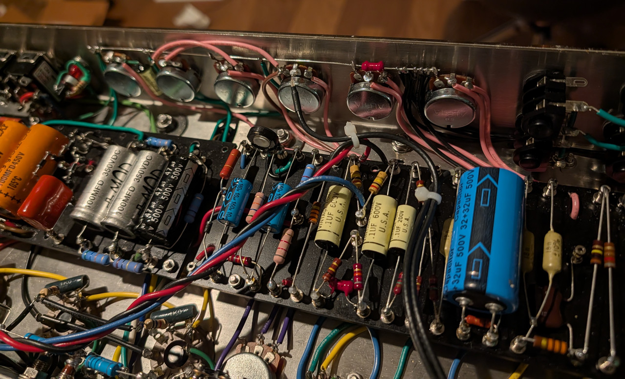
3 replaced that switched pot with a regular pot and ran a bus wire all the way across the ground lugs of the two volume pots, mid pot, and presence pot. Then I reconnected all the ground wires to the new bus. I didn't do anything else at first.
That yielded maybe a tiny improvement. From there I just one-by-one migrated every other ground to the bus, moving the 'dirty' ground there last. I heard no difference in any of these moves.
When I play the amp straight into a cabinet, the amp gets so loud that the hum seems weak. When I play the amp thru a load box I don't notice it and certainly not over the typical single coil Strat noise. And the amp sounds great, I'm super pleased with the tone.
But I still think it's not quite right. I was wrong when I said the amp is silent with V2 pulled. There is still a tiny amount of hum even with V3 pulled, very faint but audible.
Early brewers were primarily women, mostly because it was deemed a woman's job. Mesopotamian men, of some 3,800 years ago, were obviously complete assclowns and had yet to realize the pleasure of brewing beer.
Helmholtz wrote: ↑Sat Sep 26, 2026 7:43 pm
How did you wire the fuse?
Best post a drawing of your grounding scheme.
What do you mean with the "ground wire"?
The CT wire goes to the fuse, the fuse goes to the negative terminal of the main filters.
I originally had the ground wire for the main filters connected to a ground lug bolted to chassis near V7. The wire from the fuseblock (that the CT is connected to) was also originally connected to that same lug. But I moved that connection from that lug to the negative terminal of main filters. Basically to the other end of that ground wire. Then, the very last wire that I moved from a ground lug to the ground bus was that ground wire. I listened each time I relocated a ground. It is now connected (same wire actually) to the very end of the bus at the Presence control.
So right now every ground connects to this ground bus except the speaker jacks and output tube cathodes. The speaker jacks and output tube cathodes (thru 1 ohm resistors) are grounded to the same lug bolted to chassis between V4/V5. The ground bus has a wire from between Vol1/Vol2 to a bolt on chassis between input jacks. That's the only place it connects to chassis.
Early brewers were primarily women, mostly because it was deemed a woman's job. Mesopotamian men, of some 3,800 years ago, were obviously complete assclowns and had yet to realize the pleasure of brewing beer.
All the ground currents of the local grounds connected to the bus etc. need to return to the negative end of the reservoir cap, which is the "only true ground" as R.G. Keen calls it.
If I understand correctly, the chassis is grounded at 2 points at least.
So ground currents will be running through the chassis, which can be a problem.
Ideally the chassis should only be used as a shield and not as a ground conductor.
Whenever the chassis is grounded at more than one point, it gets "trial and error".
Helmholtz wrote: ↑Sat Sep 26, 2026 9:02 pm
All the ground currents of the local grounds connected to the bus etc. need to return to the negative end of the reservoir cap, which is the "only true ground" as R.G. Keen calls it.
If I understand correctly, the chassis is grounded at 2 points at least.
So ground currents will be running through the chassis, which can be a problem.
Ideally the chassis should only be used as a shield and not as a ground conductor.
Whenever the chassis is grounded at more than one point, it gets "trial and error".
I'm just beginning to think it's not the grounding. Maybe it's something else.
Early brewers were primarily women, mostly because it was deemed a woman's job. Mesopotamian men, of some 3,800 years ago, were obviously complete assclowns and had yet to realize the pleasure of brewing beer.
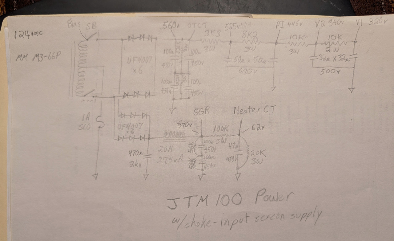
I just had the idea to split the two sections of the PI 50uFx50uF/600vdc can filter cap. It was just a 10k resistor between B+ and the PI supply because of the choke-input screen supply being separate. So I put a 3k3/3W resistor between B+ and the first section and then a 8k2/3W resistor between that new node and the PI supply. The voltages stayed about the same but the hum did come down to a new low. It's actually almost acceptable now. I've had many Marshalls that were worse.
Updated Power Supply schematic
New ground bus
Early brewers were primarily women, mostly because it was deemed a woman's job. Mesopotamian men, of some 3,800 years ago, were obviously complete assclowns and had yet to realize the pleasure of brewing beer.